Column Buckling Analysis
Determine the critical buckling load for a compression member using Euler formula per classical stability theory. Checks slenderness ratio, critical stress, and utilization.
About This Calculator
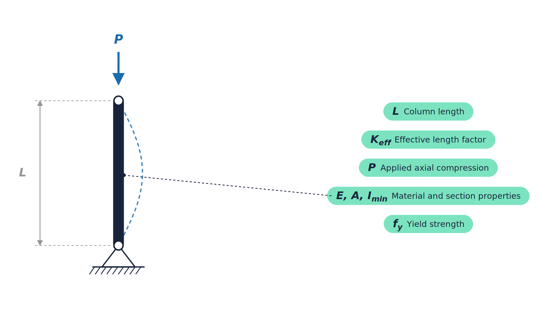
This calculator finds the elastic (Euler) critical load of a compression member and its design flexural buckling resistance to BS EN 1993-1-1 clause 6.3.1, which governs. Method: the effective length is L_e = K L, with K = 1.0 for pinned ends, 0.7 for fixed-pinned, 0.5 for fixed-fixed and 2.0 for a cantilever. The radius of gyration about the weak axis, r = √(I / A), gives the slenderness L_e / r, and the Euler load is P_cr = π² E I / L_e². The non-dimensional slenderness is λ̄ = √(A f_y / P_cr). The buckling curve then gives Φ = 0.5 (1 + α (λ̄ − 0.2) + λ̄²) and the reduction factor χ = 1 / (Φ + √(Φ² − λ̄²)), not more than 1. The design buckling resistance is N_b,Rd = χ A f_y / γ_M1, and the design load is reported as a utilisation of it. Inputs are the length, end fixity, cross-section area, weak-axis second moment of area, Young’s modulus, yield strength, design axial load, the imperfection factor α for the buckling curve (a0 = 0.13, a = 0.21, b = 0.34, c = 0.49, d = 0.76, from BS EN 1993-1-1 Table 6.2) and the partial factor γ_M1 (1.0 in the UK National Annex). Assumptions and limits: a prismatic member in a Class 1, 2 or 3 section under centric compression, buckling about the weak axis. The buckling curves allow for initial bow and residual stresses. Torsional, torsional-flexural and lateral-torsional buckling, combined bending and compression, and Class 4 sections are not covered. Typical uses: struts, braces and props, A-frame and sheerleg legs, temporary works, and quick checks of compression members before a full member design.
Referenced Standards
- Timoshenko and Gere, Theory of Elastic Stability
- BS EN 1993-1-1, clause 6.3.1 (flexural buckling resistance)