Lug Analysis
Evaluate the load capacity of a pin-loaded lug by checking three failure modes: bearing, net tension, and shear tearout. The governing capacity is the minimum of the three.
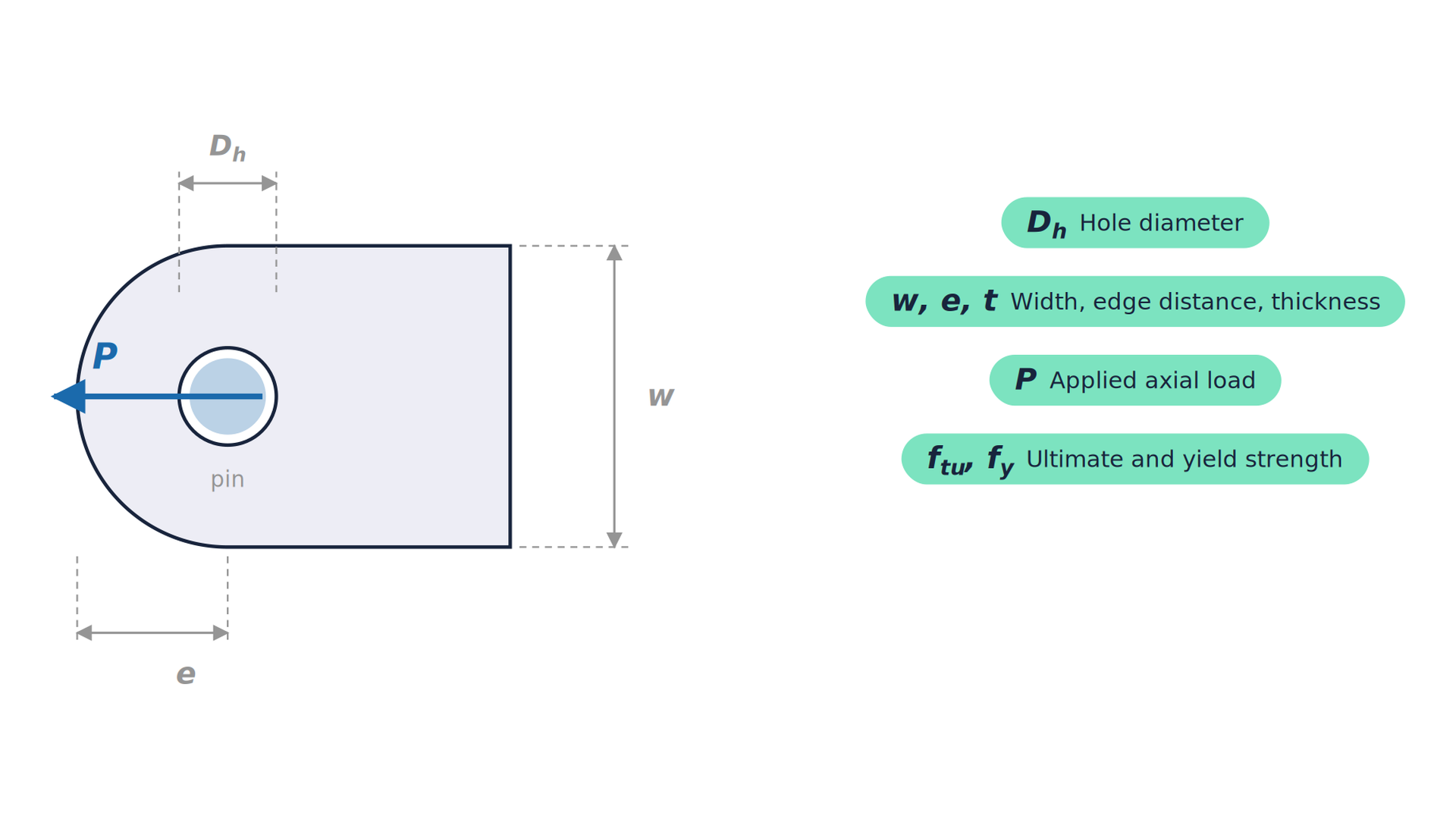
About This Calculator
This calculator checks a pin-loaded lug under in-line (axial) load against the three classic failure modes and reports which one governs. Method, after Bruhn: bearing on the pin hole, with a capacity of 1.5 f_y × D t; net tension across the hole, f_tu × (w − D) t; and shear tear-out of the material beyond the hole, 0.6 f_tu × 2 (e − D/2) t. The governing capacity is the smallest of the three, and the applied load is reported as a utilisation of it, with the stress and utilisation for each mode. Inputs are the lug thickness and width, the hole diameter, the edge distance from the hole centre to the end of the lug, the material’s ultimate and yield strengths, and the applied load. Assumptions and limits: load in line with the lug, a close-fitting pin and a straight-sided lug. The capacities are based on material strength without a factor of safety, so apply the factor required by the governing code or lifting standard. Off-axis and transverse loads, cheek plates, the pin itself (bending and shear), dishing of thin lugs and the weld to the parent structure need separate checks. For lifting equipment, the dynamic and design factors of the relevant standard, such as DNV-ST-0378 for offshore lifting appliances, normally govern the allowable load. Typical uses: padeyes and lifting points, shackle and pin connections, A-frame and boom pins, and pinned structural joints.
Referenced Standards
- Bruhn, Analysis and Design of Flight Vehicle Structures (lug analysis)
- DNV-ST-0378, Offshore and platform lifting appliances