Simply Supported Beam (UDL)
Calculate reactions, maximum bending moment, and maximum deflection for a simply supported beam under a uniformly distributed load.
About This Calculator
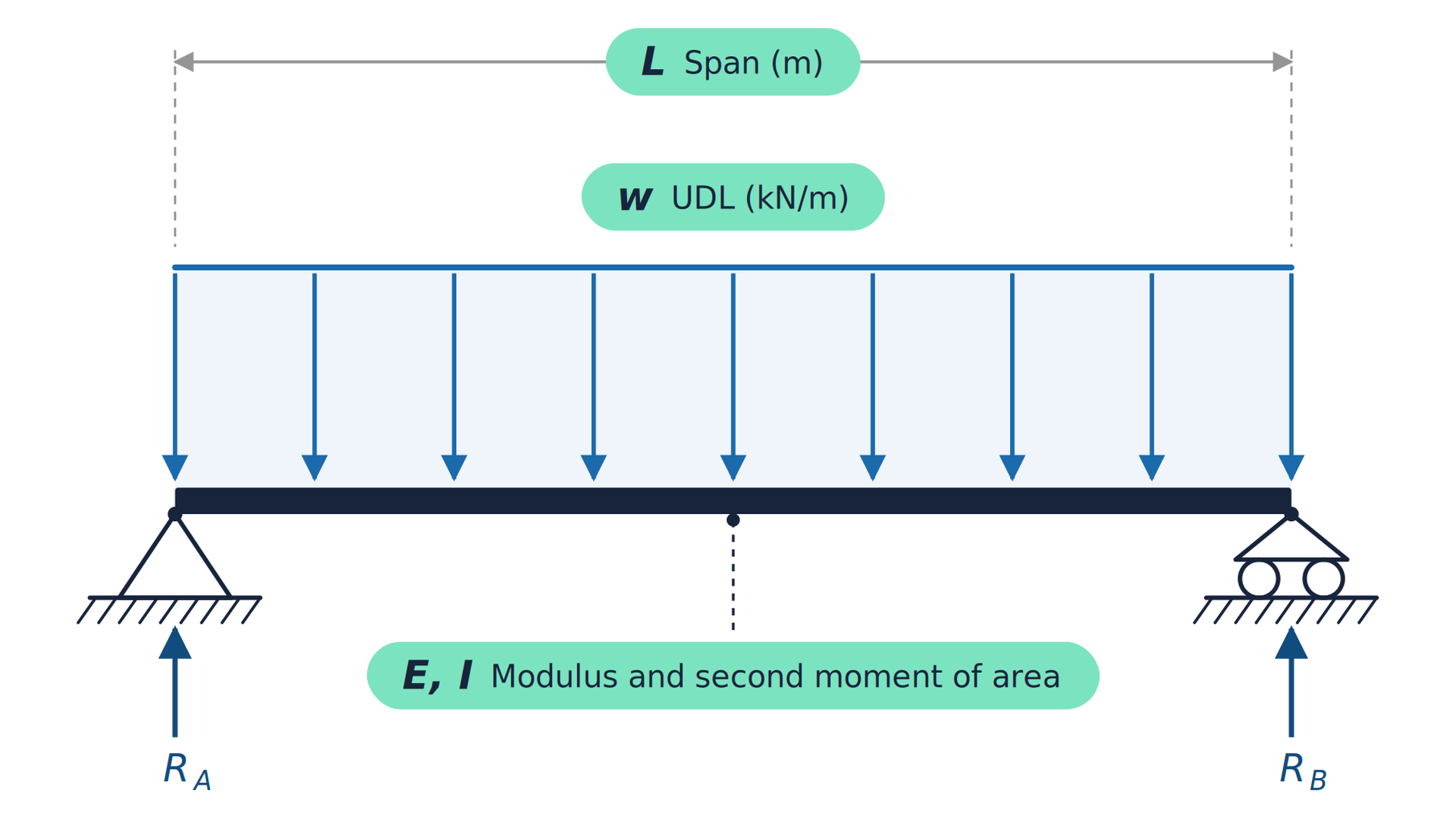
This calculator gives the support reactions, maximum bending moment and maximum deflection of a simply supported beam under a uniformly distributed load along its whole span, then checks the section to BS EN 1993-1-1. Method: classical beam theory for a beam on a pin and a roller. Each reaction is w L / 2, the maximum bending moment at midspan is w L² / 8, and the maximum deflection at midspan is 5 w L⁴ / (384 E I). The section checks are the design bending resistance M_c,Rd = W_pl f_y / γ_M0 (clause 6.2.5), the design plastic shear resistance V_pl,Rd = A_v (f_y / √3) / γ_M0 (clause 6.2.6), and the deflection against a limit of span / n. Inputs are the span, the design (factored) load for strength, the unfactored load for deflection, Young’s modulus, the second moment of area, the plastic section modulus, the shear area, the yield strength, the partial factor γ_M0 (1.0 in the UK National Annex) and the deflection limit, typically span / 200 to span / 360 depending on use. The defaults are for an IPE 300. Assumptions and limits: a prismatic, linear elastic beam in a Class 1 or 2 section, with small deflections and loads acting through the shear centre. The bending check assumes full lateral restraint to the compression flange: lateral-torsional buckling (clause 6.3.2) is not checked. If shear exceeds half the plastic shear resistance, the bending resistance must be reduced to clause 6.2.8. Self-weight (unless included in the load), point loads, cantilevers and continuous spans are not covered. Typical uses: quick first-pass sizing of beams, walkway and platform members, pipe and cable tray supports, and checking a member before a full design.
Referenced Standards
- BS EN 1993-1-1 (section resistance and deflection limits)
- Young and Budynas, Roark’s Formulas for Stress and Strain