Beyond Design for Manufacture…
Recently I put together a lunch and learn on Design for Manufacture for the team, what quickly became apparent, is that Design for Manufacture (DFM) is just the start in a long list of considerations a design engineer needs to make when designing a component or system. The following article is a summary of the teams conversations, with all team members contributing, sharing their experiences and lessons - it was a great first session on the subject.
At Subco, we learn together and like to share it with others.
From DFM to DFM+ATOM
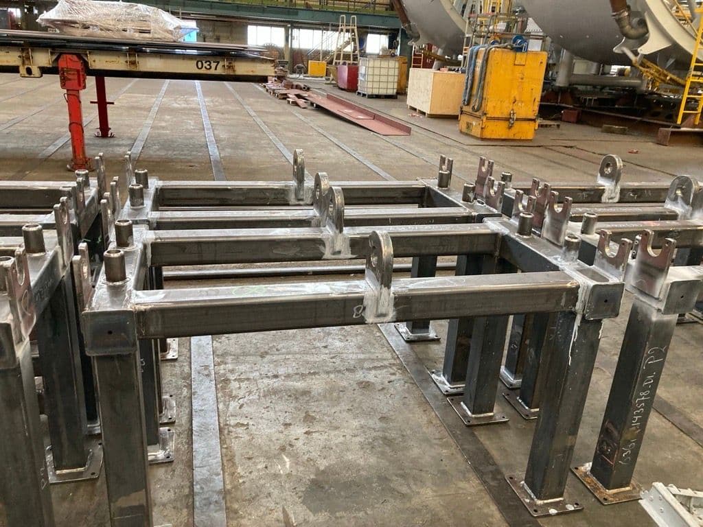
Design for manufacture is the one everyone's aware of. But there's so much more to it when you think about the full life cycle of the equipment, especially in the bespoke design work we do. As well as manufacture, you have to consider how the equipment will be assembled, tested, transported, operated and maintained. I've been calling that DFM+ATOM.
All of that combined makes for a good design, and you can't do any of it in isolation. We won't always have the information to fully define every stage, but it should always be on our minds as we design. There's plenty the acronym doesn't spell out, too. I've bundled painting and coating into manufacture, and maintenance rolls naturally into decommissioning and getting equipment back out of the field. Regardless of how you define the acronym, the important things is to be aware of the full life cycle of a component / system when you are designing it.
Know where the cost sits
Running in parallel with all of this is cost: what it costs us, or our clients, to produce, install and maintain what we design.
As engineers, we're pretty good at hitting technical and functional specs. Someone tells us it needs a safety factor of two, and we make sure it has one. Someone tells us it's got to lift 5 tonnes, and that's not a problem. The real challenge is doing it in the most efficient way possible, and by efficient I mean cost-effective and optimum for everyone who uses it through its life. We might design the perfect bracket or lever, and then the person who has to use it can't reach it because it's too high. It's those little things that never arrive in a technical spec, and that nobody defines up front, that we're just expected to know.
It helps to know where a job sits on the cost scale. Picture a really specific problem with lots of interfaces, where the answer turns out to be a small bracket. It's cheap to make and cheap to assemble, and it doesn't need testing. But it has to be fully analysed, verified and fatigue assessed, and installing it might need a crane or vessel support. Most of the cost there is in the engineering, so spending plenty of time up front on the design is justified. That's where the value is.
Flip that around to an A-frame support grillage or a 30-tonne lump of steel. The design side is fairly simple, the manufacturing cost could be huge, and the rest is run-of-the-mill. Spending weeks designing the world's best frame for 30 tonnes of steel adds very little for the client, because the bulk of the cost is in the fabrication. The effort is better spent making it easy and cheap to build.
Manufacture
Don't specify what you don't need
Choose materials for what the job actually needs, and for availability, lead time and cost. We shouldn't be specifying an exotic steel that isn't readily available on the market, or going for super duplex when it isn't required.
The same goes for sections and plate. Is it European sections for a European market, or Japanese sections for an Asian one? A size might be in the catalogue ten pages deep, but can the preferred fabricator actually get it in the lead time? Then there's material quantity. There's no point having five plates at 5 mm on one fabrication, another six at 6 mm, a few at 8 mm and two more at 20 mm. Consolidate on common plate thicknesses and member sizes, and you simplify both the design and the shopping list for whoever has to buy it all in.
Martin pointed out that this bit us recently. We'd specified UC sections, which you can get almost anywhere, but the client's chosen fabricator was European and wanted HEAs and HEBs. It was right that it came up while engineering was still designing, and luckily it was an easy change. It's far worse when it surfaces at procurement, after everything's been designed and signed off, and we have to go all the way back. Some of those changes can be quite extreme.
Question the machining
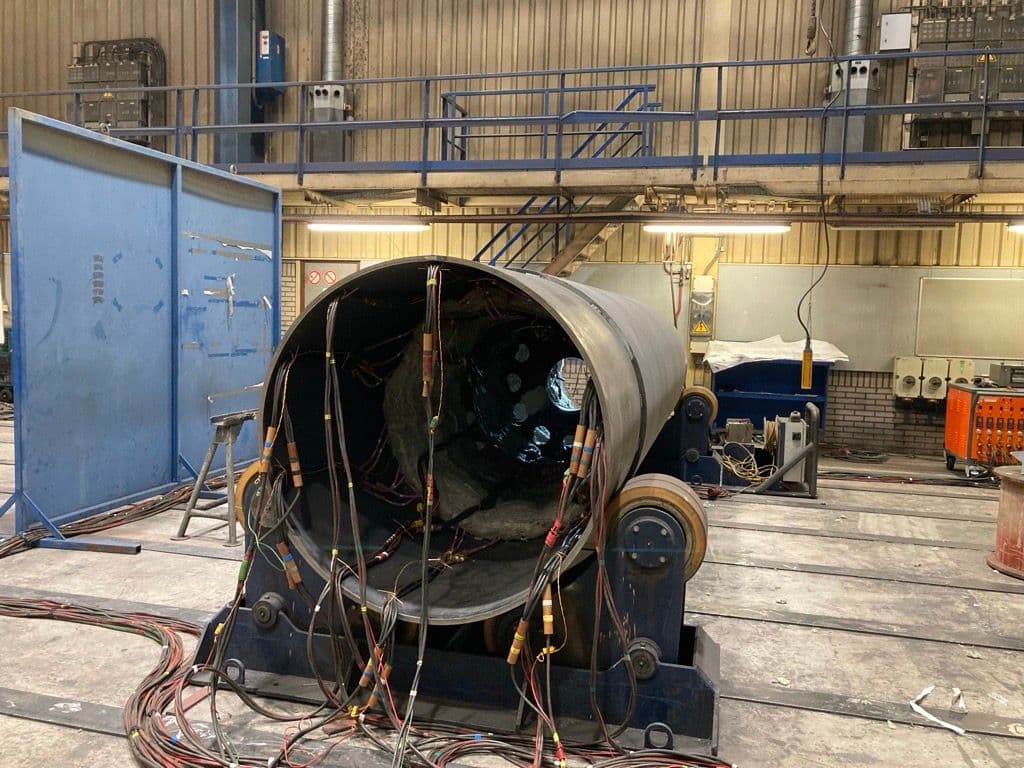
All machining adds cost, and many of the fabricators and suppliers we use are limited in what they can machine. If a fabrication is too big for their machines, they have to sub it out, and it costs a lot more. Martin added a useful rule of thumb: a typical machining envelope is around a 1.5-metre box. Milling two surfaces a metre apart is fine, but once you go past two metres the cost jumps.
So as designers we should be asking some questions. Does this really need to be within machine tolerance? Would the profile tolerance from laser cutting be good enough? Can everything be machined from one side, so the part doesn't have to be flipped and set up again?
Sometimes a jig does the job instead. Say you've got four foundation points that need to line up perfectly with something on site. Instead of machining them, make a cut plate that simulates those four positions and build up from it. A classic example is lining up holes through clevis plates. Rather than machining through, put a bar the same size as the pin through the holes, then weld everything in position so the holes can't move during welding.
Every fabricator has its preferences
There isn't always a right or wrong way. A fabricator with 20 welders to keep busy will want to weld everything. Another with a press brake to keep busy will offer to bend some 6 mm plate into an angle rather than buy one in. We can't control that, and we'll often get asked whether we can substitute one thing for another. It's worth being aware of.
Beyond that, manufacture covers how plate is cut and formed (cold formed, cold pressed or hot rolled), welding access and the cost of welds and NDT, geometric tolerancing, and coatings from painting and galvanising to sherardising and cladding. Each of those manufacturing considerations deserves a dedicated deep-dive session - one for the future.
Assembly: interfaces, tolerances and room for a spanner
A lot of us have worked in companies where we designed equipment, sent it out to be fabricated, and got it back to assemble ourselves.
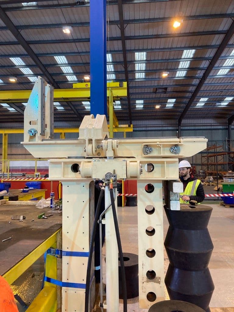
The key consideration is interfaces. On a typical subsea vehicle, you've got cylinders, fabrications, tracks, a thruster, a dredge pump, bolts and energy chain guards all coming in from different suppliers. It's our job to make sure it all comes together and fits where it's meant to.
Then there are tolerances. Depending on the drawing and the size, a fabrication might be held to ±0.5 mm, ±2 mm, or ±10 mm or more on a large fabrication. If we don't put a tolerance on the drawing, the dimension is completely uncontrolled and we're just assuming the fabricator will hit it. That's quite dangerous. Bolt or pin three or four fabrications in a row, and the two end points can be a long way out. Where alignment is critical, do a tolerance stack-up review and plan for adjustment, using shims or a bolted bracket that can bring everything back into line.
Movement matters too. Trunnion-mounted cylinders swinging round can end up very close together, and that's where interfaces, tolerances and actuation ranges combine into exclusion zones and space claims. Clash-check items as they move through each stage, not just in their final position on the model.
It's not only whether things fit in their final state, but whether you can get them in as the assembly builds up. If you start with the tracks at the bottom, can you build the fabrication on top and then bring the cylinder in from the side with the track already next to it? Can you slide that cylinder back out later? A production manager will plan the build, but they can only work with what they're given. On subsea vehicles especially, the hydraulic and electrical teams also need room to route pipes and fit cables.
Workshop handling
We do plenty of lift calculations and lift plans for the finished product, but before that the workshop has to handle it. Overhead cranes are typically 5 or 10 tonnes, and not many workshops have 20 tonnes unless they're really big. Can the parts be lifted, flipped 180 degrees or upended? That may mean adding extra lift points.
Stability is part of the same question. A fabrication that can't rest on its own and has to be constantly stooled or held is highly frustrating for the workshop. It's usually easy to fix with dog legs or a simple bracket.
Bolts
It's easy to keep increasing bolt sizes in a calc and a model. But above about M20 or M24, you're into hydraulic tensioner territory. Rattle guns won't reach the torques, and you need extra equipment. A flange with 36 bolts that all need tensioning is a far slower job than M12s that three or four people can torque at once. Assembly shouldn't drive bolt sizing, but ever-bigger bolts do have a knock-on effect.
Chris added a big one: make sure you can actually get a spanner on the nut. When we do the assembly deep dive, we'll pull out the clearances needed and get a better feel for the physical size of tensioners and hydraulic torque tools.
Testing: will the design survive its own test?
Testing varies massively. A proof load test can be as simple as a one-off local check on a pad eye. A system load test might use water bags to load an A-frame, sheave, wire rope and pins together. Winches and bespoke systems involve a lot of functional testing, through FAT, SAT and commissioning, and HPUs and pipework need pressure testing.
We don't often get involved in testing ourselves, but we need to design for it. For a 25-tonne winch, is there a grillage with that capacity, and room for it in the workshop? That's quite often the limiting factor. A functional test also takes a lot of setting up. Does the winch need power, or an HPU and a generator? Does it need a stunt box? (which is a simplified version of the final controller)
Then check the test load path. We might rate a pad eye at a 120-tonne safe working load on the basis that the load is distributed through the main legs of the frame, as intended. When it comes to the load test, someone might put a cylinder or two right next to the pad eye and load up the local structure. That's a concentrated 120-tonne reaction we haven't studied. Site tests need the same thinking. Water bags are common, but is there enough weight available on site to recreate a 120-tonne load?
Transport: the dimension nobody expected
This is where things start slipping out of our minds as engineers, and we think it's someone else's problem. But we need to know where the equipment is being built, where it's going and how it will get there.
Everyone knows a 4-metre-wide load will be hard to move by road. The problem is kit designed to just under 2.9 metres. Everyone thinks it's fine, then the low loader turns up and something is sticking out of the side. Suddenly it's 3 metres wide, it's an abnormal load, and it needs two days' notice to move. That can really disrupt a project. Weight matters too: around 44 tonnes is typically the most you can take on UK roads.
Chris pointed out that height is just as big an issue on UK roads. Sometimes a normal lorry turns up, the load is too high, and it has to go away while a low loader is found. Martin added packaging. An HPU might have its big side panel packaged separately, or kit might need stooling for transport. Put a wooden box on the side of that HPU and you can end up over 2.9 metres without anyone intending it.
Beyond the road, check barge sizes and capacities if you're shipping. Check the workshop's shutter doors too; building something that's too wide to get out through the doors it came in by is a classic. Twenty 1-tonne items are easy with a 10-tonne crane, but once they're assembled into one 20-tonne unit, it can't be lifted back out of the workshop. Think about how it will be lifted off the lorry on site and where it will go. If someone asks for everything to fit in a 20 ft ISO container, which people love to work to, be aware of what that constrains.
Assumptions change, too. Martin has seen it be cheaper to drive something down to Southampton than to ship it from the Port of Blyth, and when that happens the PM will follow the money. So even when transport limits were agreed at the start, keep an eye on them.
Operation: the little things that slip through the net
Operation is core to our design. We've got a technical spec, the client's functional requirements and the environmental data. But some things sit outside the spec, and the overarching one is safety. People assume what we deliver will be safe. They might not ask for an FMECA or a design safety review, but as professional engineers we have to make sure what we produce is safe. That might be a full failure modes, effects and criticality analysis, or a quick session with a few people in the office, running through the likely failure modes and checking there are enough mitigations and safety gates.
Even on something as simple as a bracket or a lever, we should err on the side of failing safe:
- Dead-man controls, so the system stops if the operator lets go or is taken ill.
- Controls that need positive engagement, and drop back under gravity to stop everything when released.
- Gates that shut and lock behind you, rather than swinging open in the wind.
- Moving parts that can be pinned and locked in position.
Ergonomics will never be in a technical spec, but you're expected to understand it. Take a control panel on an HPU that's been lifted onto a 300 mm pedestal. Now you can't read the HMI or reach the buttons, especially if you're short like me. Or you open a control cabinet and the fuses are right at the top, out of reach without a step. Line of sight is another common one: you can't safely control an outboarded A-frame if something in front of you blocks your view of the cylinders or the payload. Even the rise and going of steps is set by standards for a reason; get it wrong and people trip.
Martin added warnings, which we rarely think about but are ours to specify. That means harness attachment point labels, hot-surface and low-headroom warnings under the Machinery Directive, and yellow-and-black zebra marking wherever someone might try to get at something they shouldn't. A lot of this comes with experience and a few bad mistakes. If we share those experiences, everyone gets there quicker.
Maintenance: the one time it's needed, it has to work
We're good at duty cycles and design lives, and at making sure things are strong enough not to fall apart. What's often not on our minds is the maintenance schedule, and the engineer who has to go round and inspect the equipment.
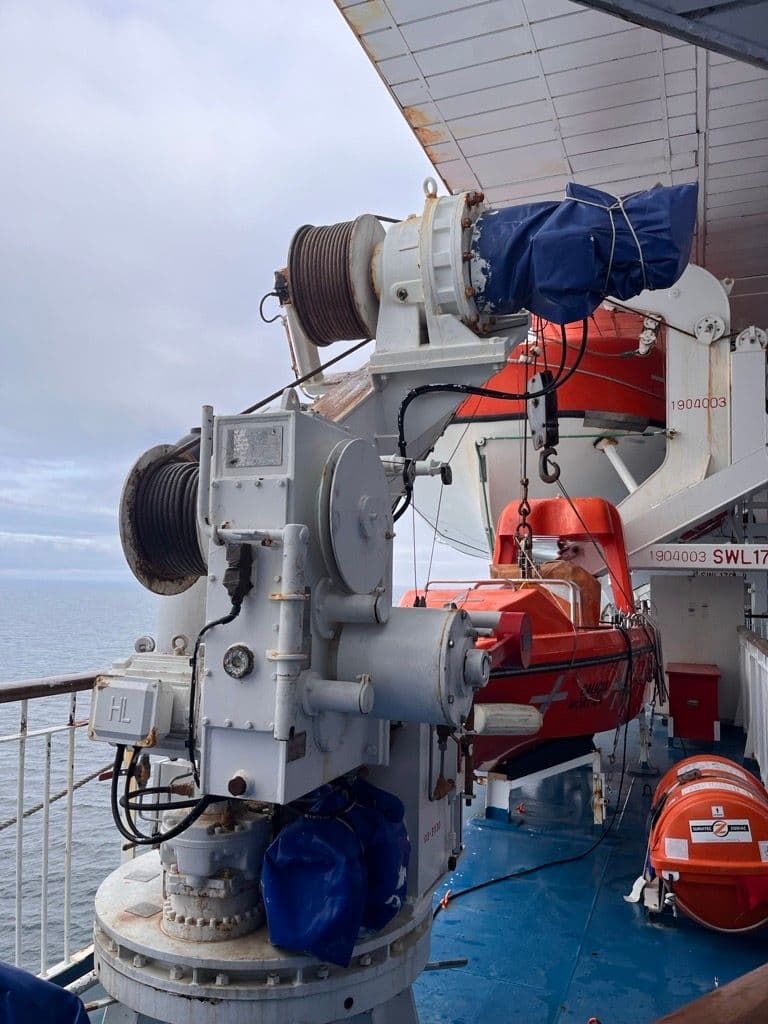
On a ferry over to Spain, I spotted a davit on deck. It makes that crossing and back every day, and you could see the bolts were corroded. It's the kind of kit that hardly ever gets used, but the one time it's needed, it has to work. Some of our equipment is exactly the same.
Bolts need inspecting regularly, every six or twelve months depending on the schedule, and critical welds, especially on lifting gear, need checking too. Can people reach them safely, see what they need to see, and take the measurements they need to take?
Think about replacing key components. An A-frame is fantastically stable with two cylinders, but take one off after a failure and it becomes very unstable. How do we plan for that, and can it be stowed or pinned in a safe position? The same goes for re-reeving winch wire rope through sheaves and running it around the deck.
Rather than sending someone up to height with a grease gun, fit a manifold block at the bottom so the pins can be greased from ground level. Automatic greasing systems go a step further and keep grease pumping without anyone going near the equipment.
Matthew raised access for heavy components. If an electric motor has to come out, is there overhead height to lift it? Where does it land, and can it be supported? Could you extend a plate so the drive can rest on it? We used to fit a lot of pin catches, small fabrications that cradle a big pin as it's drawn out so it doesn't suddenly drop, and they help when it goes back in, too. The guys on site will be big fans if you plan for this.
Finally, decommissioning. Much of the campaign equipment we design for vessel decks, such as cable-lay equipment, may only be in service for a couple of years, or for a single six-month summer campaign. Then it all gets stripped off and the back deck is cleared for the next job. If we've welded everything to the deck, someone will be going round grinding it all off. That might be fine, but it might be a problem, so it's worth thinking about at the design stage.
Flag it early, even if it isn't yours to solve
"When you put it all together like this, it's a tough job being a design engineer. Anyone can design a bracket. It's when you consider all those things across the full project life cycle, along with the technical spec you're given at the start."

Richard Ward
The spec says it has to take 5 tonnes, or it has to be a roller of a certain size. That's just one part of it. As design engieneers, everything that comes after is often in our remit too.
We won't always have the answers, but be we can be proactive in highlighting concerns. If fabrications are getting bigger on a project, we can flag it to the PM: "By the way, we're over 2.9 metres now, so that's an abnormal load on the road."
What's next
That skim across the whole subject took the full session, which says a lot about how big it is. So we're breaking it into focused deep dives.
As Martin said at the end, a lot of this gets learned the hard way on the shop floor, by fixing things after they've gone wrong. The aim of the series is to give our engineers that insight at the design stage instead. We'll share more here as it goes.
Category:
Blog
Written by:
Richard Ward