Model-Based Definition
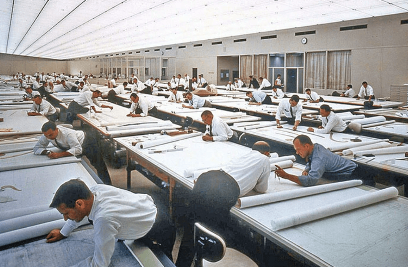
The way we create and share designs in engineering has evolved significantly over the years. Initially dominated by hand-drawn plans, 2D drawings were universally understood and widely used across industries, providing a clear blueprint for engineers, builders, and manufacturers.
However, the advent of digital technology brought about transformative changes. The shift to 3D modelling allowed engineers to construct digital versions of their designs, offering a more comprehensive view and a better understanding of how components fit together in the real world.
Model-Based Definition (MBD) represents the latest advancement in this progression. MBD integrates all essential design information within a 3D model, reducing reliance on traditional paper drawings. This method enhances clarity and speeds up the entire design process by centralizing information in an easily accessible digital format. While MBD has been embraced in industries like aerospace and automotive for some time, the mechanical sectors, including offshore, marine, and renewables, have been slower to adopt this technology. This lag highlights the challenges and opportunities for wider implementation and acceptance of MBD in these crucial areas.
What is Model-Based Definition?
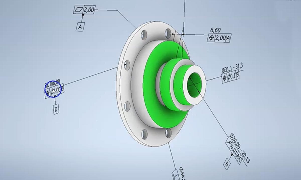
Model-Based Definition, or MBD, is an approach that incorporates all product and manufacturing information within a 3D CAD model. This method centralises data such as geometrical dimensions, tolerances, and specifications right in the model, effectively rendering traditional 2D drawings obsolete.
Key Components of MBD:
- Geometric Dimensioning and Tolerancing (GD&T): This includes detailed annotations within the 3D model that specify the allowable variation in geometry.
- Material Specifications: Captures information about the materials to be used, detailing standards and properties essential for manufacturing.
- Process Requirements: Provides specific instructions on manufacturing processes, finishing details, and quality assurance measures.
- Component and Assembly Details: Details information on individual parts and their relationships within the assembly, crucial for both manufacturing and assembly processes.
The digital revolution in the late 20th century brought about a significant shift with the introduction of Computer-Aided Design (CAD) systems. These systems allowed engineers to create digital 2D drawings on computers, which was a substantial leap forward in terms of speed and editing capabilities. Yet, it was the development of 3D CAD technologies that marked a turning point for the engineering and manufacturing sectors.
Key Milestones and Technological Advancements:
- Introduction of 3D CAD Systems: The availability of 3D CAD software in the 1980s allowed designers to create three-dimensional models that could be viewed and manipulated on screen. This not only improved the accuracy of the designs but also enabled a clearer understanding of complex structures and assemblies.
- Development of Parametric Modelling: In the 1990s, parametric modelling techniques were introduced, allowing changes made to one part of the model to automatically update related components. This interconnectivity reduced errors and improved the efficiency of the design process.
- Advancements in Computing Power: As computing power increased, so did the capabilities of CAD software. More complex models could be created and stored, paving the way for integrating additional information like material properties and process parameters directly into the CAD model.
- Standardisation of Data Exchange Formats: The creation of standardized data exchange formats such as STEP and IGES enabled different CAD systems to communicate with each other. This was crucial for collaborative projects and further supported the adoption of MBD, as it ensured that comprehensive design information could be shared across platforms without loss of detail.
The convergence of these technological advancements facilitated a shift towards Model-Based Definition. By integrating all necessary data directly into 3D models, MBD has not only streamlined the design and manufacturing processes but also opened up new possibilities for innovation and efficiency in product development.
The Persistence of 2D CAD
Despite the significant advancements in 3D modelling and the adoption of Model-Based Definition, 2D CAD remains indispensable in many sectors.
Reasons for Continued Reliance on 2D CAD:
- Simplicity and Accessibility: 2D CAD is generally simpler and more accessible for those without specialised training in advanced 3D software, making it ideal for straightforward projects.
- Compatibility and Legacy Issues: Many industries have extensive archives of 2D drawings that are crucial for ongoing operations. Converting these to 3D models requires significant resources, and many manufacturing and construction processes mandate 2D drawings for compliance and regulatory purposes.
- Cost-Effectiveness: The transition to 3D CAD systems and the associated training can be costly. Smaller enterprises often find 2D systems more budget-friendly as they require less powerful computing resources.
Advantages of 2D CAD That Still Hold Relevance Today:
- Clarity in Specific Applications: In fields like civil engineering and some types of architectural design, 2D drawings provide unparalleled clarity. Topographical maps and floor plans, for instance, are often more effectively communicated through 2D representations.
- Efficiency in Production and Communication: In manufacturing settings, 2D drawings are essential for the production lines and remain the most efficient way to communicate complex fabrication details quickly.
Utility in Concept Work:
- Speed in Conceptualisation: For initial concept work, 2D drawings are typically faster to produce and modify. They allow designers to rapidly iterate and convey ideas without getting bogged down in the complexities of 3D modelling.
- Handling Large-Scale Projects: In projects involving large assemblies or complex geometries, such as full vessel general arrangements, 2D CAD is often more practical. 3D files in such scenarios can become unwieldy due to the sheer volume of data and intricate details involved.
Despite the growing capabilities of 3D technologies, these factors ensure that 2D CAD remains an essential tool in the engineering toolkit, balancing the push towards innovation with practical, on-the-ground needs.
Barriers to Adopting 3D Model-Based Definition
Transitioning to Model-Based Definition (MBD) offers significant advantages for engineering and manufacturing processes, yet several barriers can impede its widespread adoption. There are several common challenges and obstacles that companies may encounter when shifting from traditional 2D CAD systems to a comprehensive 3D MBD approach.
Technical Barriers:
- Software and Hardware Requirements: MBD requires advanced software capable of handling detailed 3D models and embedded data, which can necessitate substantial upgrades to a company’s IT infrastructure. Additionally, employees need training to proficiently use these new tools, which can disrupt ongoing operations.
- Data Management and Integration Issues: Managing the vast amount of data within MBD systems, including integration with existing systems, poses a significant challenge. Companies often struggle with data consistency and maintaining the integrity of model information across different platforms.
Financial Barriers:
- High Initial Costs: Implementing MBD involves significant upfront costs. These include purchasing licences for advanced CAD software, upgrading hardware, and training staff. For many companies, particularly small to medium-sized enterprises, these costs can be prohibitive. This is especially true where companies have a substantial product portfolio database which would need to be migrated and converted to this new way of working.
- Ongoing Maintenance and Support: Beyond initial setup and training, ongoing maintenance and technical support for sophisticated MBD software can be costly. These expenses include regular software updates, system maintenance, and possibly hiring specialised IT staff to manage complex 3D CAD systems.
Industry Readiness:
- Adoption by Suppliers and Fabricators: A major hurdle in adopting MBD is the readiness of the entire supply chain to handle these systems. Many fabricators, machine houses, and other key players in the manufacturing industry may not be equipped to work directly from 3D models embedded with MBD data. Their processes might still rely on traditional 2D drawings, and without a critical mass of industry adoption, transitioning to MBD can be both risky and inefficient.
The Case for Moving Beyond 2D Drawings
Despite the advancements in 3D modelling technologies and the introduction of Model-Based Definition (MBD), 2D drawings continue to be prevalent in various engineering disciplines; how can we move past this point and fully transition to a 3D based approach, what are the potential benefits and the role of neutral file formats in facilitating this transition?
Analysing the Prevalence of 2D Drawings:
- Familiarity and Established Workflows: Many industries have long-established processes centered around 2D drawings, creating a comfort level and a perceived lower risk in continuing their use.
- Regulatory and Industry Standards: Some sectors, particularly those involving public safety and regulatory compliance, are slow to adapt due to stringent documentation requirements that often specify the use of 2D drawings.
Advantages of Fully Embracing 3D MBD:
- Enhanced Communication and Clarity: MBD provides a more interactive and detailed medium, reducing ambiguities associated with 2D drawings and improving understanding across design, manufacturing, and maintenance phases.
- Streamlined Workflows and Error Reduction: MBD minimises the need for multiple documents and constant revisions, thereby reducing errors stemming from misinterpretation or outdated information.
- Increased Efficiency and Cost Savings: The initial setup costs for MBD are offset by long-term benefits such as quicker project completion, reduced rework, and lower costs for physical document storage and management.
Storing Information Throughout Production:
- Embedded Inspection and Manufacturing Data: In MBD, each part file can carry its complete production history, including inspection dimensions and records of any defects. This data travels with the part file through every production stage, enhancing traceability and quality control.
- Dynamic Data Updates: As the part progresses through stages, updates related to process adjustments or quality checks are embedded directly into the model, ensuring that all stakeholders have access to the most current information.
Neutral File Types for MBD Transmission:
- STEP 242: An advancement over STEP 204, STEP 242 supports the embedding of product manufacturing information (PMI), making it suitable for MBD. It allows for the seamless transfer of detailed 3D models along with comprehensive manufacturing data.
- IGES and JT Files: While IGES is an older format that supports some MBD features, it is less efficient in handling complex data compared to STEP files. JT files are particularly useful for visualisation and sharing of lightweight 3D models but may not support as extensive a range of data as STEP 242.
- Advantages and Disadvantages: STEP 242 is robust in its data handling capabilities but can be complex and require significant processing power. IGES, while widely compatible, lacks the ability to carry extensive PMI effectively. JT files are excellent for quick sharing and collaboration but are not ideal for detailed manufacturing processes.
Conclusion
The shift towards Model-Based Definition (MBD) represents a significant step forward in the evolution of engineering design and manufacturing processes. By integrating comprehensive product and manufacturing information directly into 3D models, MBD offers a unified approach that enhances clarity, reduces errors, and streamlines communication across all stages of production.
Summarising the Benefits:
- Enhanced Efficiency and Accuracy: MBD facilitates a more efficient workflow by reducing the reliance on multiple documents and the need for constant revisions. This integrated approach helps to minimise errors commonly associated with manual data transfer and outdated documents, thereby improving overall accuracy and reliability.
- Improved Communication: With all relevant data embedded within the 3D model, MBD improves communication among design, manufacturing, and quality assurance teams. This comprehensive information sharing boosts collaboration and helps to ensure that all parties have a clear and consistent understanding of the project requirements.
- Cost Reduction: Over the long term, adopting MBD can lead to significant cost savings. These savings come from reduced material wastage, decreased time spent on document management, and lower likelihood of costly production errors.
Considerations for Transition:
- Initial Investment: Transitioning to MBD requires an upfront investment in new software and training, which can be substantial. Organisations need to assess their current technological infrastructure and personnel skills to determine the feasibility and scale of investment required.
- Change Management: Adopting MBD involves not just technological change but also a shift in organisational culture and processes. Effective change management strategies are essential to facilitate this transition, ensuring that all stakeholders are on board and properly trained to utilise the new system.
At Subco Engineering, we are committed to pushing the agenda for the use of MBD, recognising its potential to transform engineering processes. However, we are also mindful of the economic constraints and readiness of certain companies and customers. We understand that not all are able to make the leap to MBD immediately. As such, we will continue to support traditional methodologies while advocating for and facilitating a gradual transition to more advanced, efficient, and cost-effective MBD solutions.
Category:
Case studies
Written by:

Richard Ward