Bolted Joints in ANSYS Mechanical
The if you know... you know, how to guide on modelling bolted flange connections efficiently using beam elements.

Shahriar Dalvand
Senior Mechanical Engineer
What you will learn
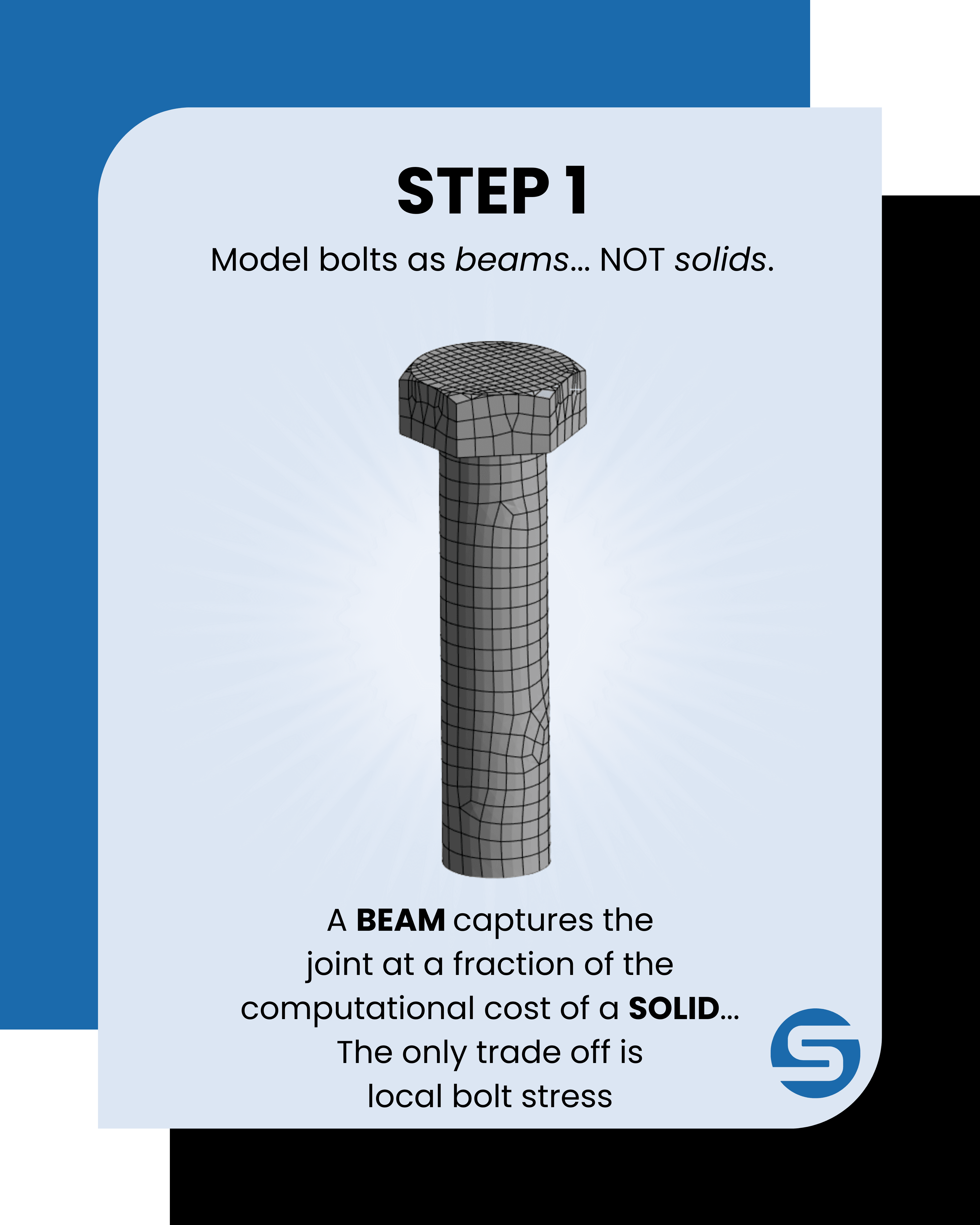
- Why bolts are represented by beam elements rather than solid bodies, and when that trade-off stops being appropriate
- What geometry preparation the approach depends on
- How to build bolt groups quickly using named selections and Object Generator
- Why bolt pretension has to be applied across two load steps
- Why flange faces need frictionless contact rather than bonded
Prerequisites
- Working knowledge of ANSYS Mechanical (Static Structural)
- Familiarity with contacts and boundary conditions in FEA
- Basic understanding of bolted joint mechanics
Why model bolts at all?
The idea to treat a bolted assembly as one continuous body, whether it's by bonding all the contacts or importing a simplified solid, completely misrepresents how the joint actually carries load.
After all a bolted connection works in two distinct ways:
- Bolts carry tension,
- Mating faces carry compression.
This distinction is so important especially whenever the project involves joint separation, load path through the assembly, contact pressure at the flange face, or bolt load under combined loading.
So then why beam elements rather than solid bolts?
The real reason is mostly computational cost.
If a solid bolt meshed finely enough to capture thread geometry and head bending carries tens of thousands of degrees of freedom, across a flange with 20 or 40 fasteners, that becomes really impractical to solve for what's already considered a secondary component.
A beam element reduces each bolt to two nodes with six degrees of freedom each. We still define the cross-section, material, and pretension properly as expected, and the beam still carries axial load, bending, and shear as the real bolt would at a gross-structural level. The only thing lost is just some local detail: thread stress concentrations, head bending, and bearing stress under the washer face and honestly for whole-assembly work, it's an easy trade to accept, since those effects need a separate sub-model anyway.
| Approach | Approximate DOF per bolt | Best used when |
|---|---|---|
| Solid bolt (3mm hex mesh) | ~38,000 | Bolt-local stress (threads, head, fillet radius) is the result of interest |
| Beam connection | ~230 | Joint load path, pretension, or flange contact pressure is the result of interest |
STEPS
Step 1: Geometry preparation in SpaceClaim
Two things need attention before the model goes anywhere near Mechanical.
Imprint the washer faces: The bolt beam has to be scoped to the washer contact area on the flange face, so that area has to exist as a separate face in the solid. I advise to use the imprint or embed tool in SpaceClaim to stamp the washer footprint onto the parent face. The result is a coincident face that can be selected independently in Mechanical.
Fill the "non-critical" features: Grease ports, bolt hole chamfers, and tight fillets outside the load path just add more mesh complexity, but without really changing the answer, so the judgement is the same for all these features: Does this actually affect the stress result I'm looking for? No... then just fill it.
Step 2: Named selections using the Worksheet view
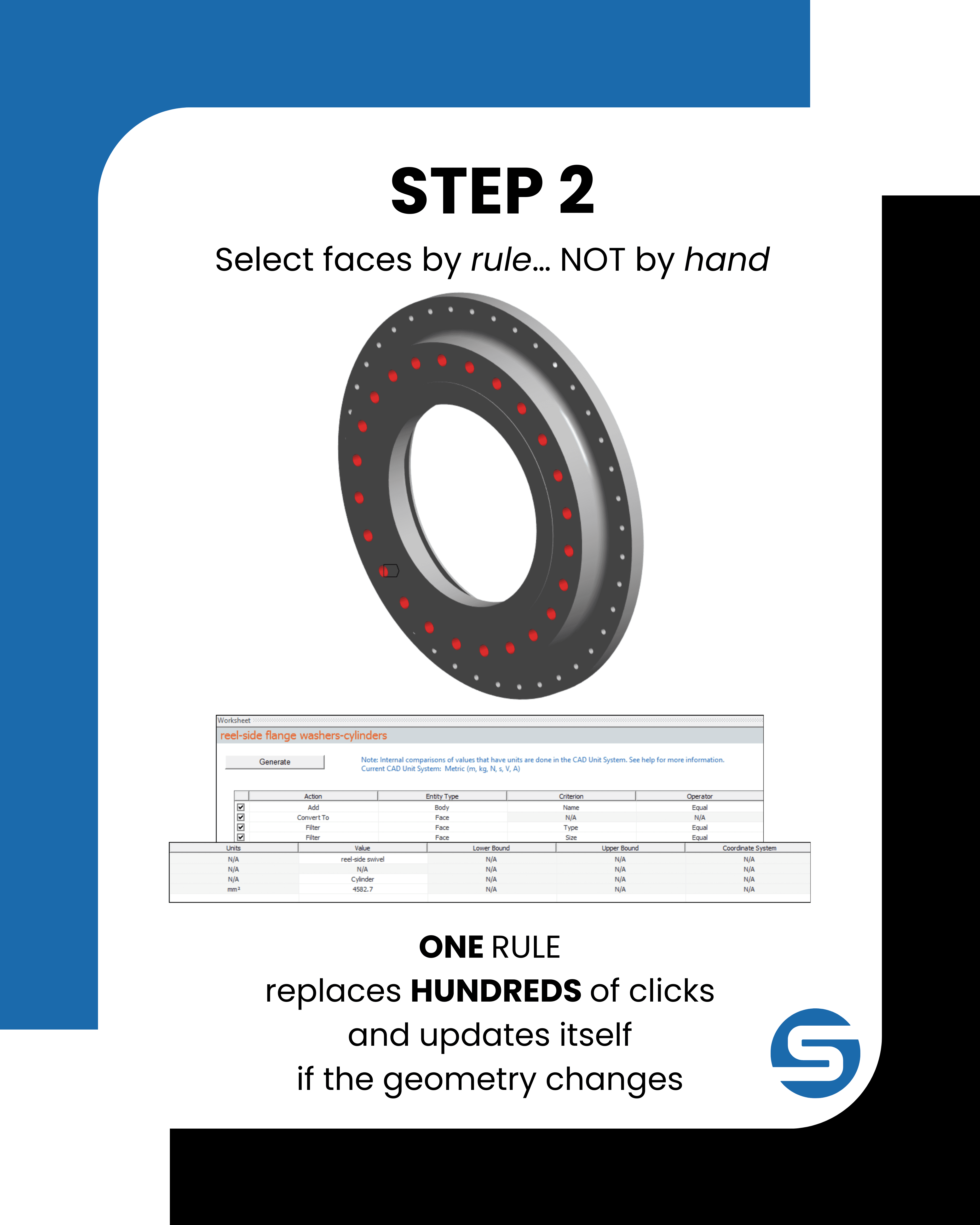
Sure, picking faces by hand is manageable on one flange and error-prone across 40 or 128 bolt holes, but the Worksheet view in the Named Selection tool instead defines selections by setting a filtering rule instead.
Setting up filters on the area rather than radius is the practical approach since area is the criteria the Worksheet actively exposes for face geometry. That way you can first select a representative hole face and just use that area value in the filter.
This same rule works for any number of holes, since we've now set it up to update independently with any geometry changes. This way we've created a reproducible selection that can be checked later rather than a manually clicked group that can't.
Step 3: What a bolt beam connection actually is
When you're doing FEA (finite element analysis) on a piece bolted together you don't usually model the actual bolt threads, nut, washer, etc. It's overkill and makes meshing a nightmare. So instead, you represent the bolt as a simple 1D line (a "beam") running from the bolt head down to where the threads engage. Give that beam the bolt's actual cross-sectional properties (diameter, material = steel) so it carries load realistically, just without the geometric complexity.
Why remote points exist
The beam is just a floating line and it needs to actually connect to the solid geometry at both ends. We do that with a remote point: software machinery that ties the end of the beam to a whole face on the real part by using constraint equations (MPC = multi-point constraint).
Why the "behaviour" setting matters (this is the key concept)
You get to choose how those invisible links behave:
- Rigid = force the face to move as if it were perfectly stiff, so it can only translate/rotate as one rigid unit tied to the pilot node.
- Deformable = the face is allowed to flex and distort naturally under load, and the remote point just averages/transfers the load without artificially stiffening anything.
So why the split: rigid at threads, deformable at washer face?
- At the threaded end, the bolt is locked into the nut/tapped hole, think in reality that interface barely deforms relative to the bolt. So rigid is the only reasonable simplification.
- At the washer face (the side under the bolt head), the surface does flex - that's a real physical bending/compression effect under a clamped load. But now if you make that end rigid as well, you're telling the solver that "this area cannot deform," which artificially stiffens that local zone on the software. And if the solver then can't put stress where it physically belongs (right around the bolt hole/washer), it just pushes that stress somewhere else instead. And at this point your result is now just wrong, not just less pretty.
Scaling up with Object Generator.
Two things make this properly work. The named selections need to be scoped appropriately, so that we've given the generator a consistent set of faces to work through. And at least one of those connection needs to be built up manually and correctly by hand first, because then that instance becomes the template that every follow up generated connection duplicates. Get those right and any group of n bolts takes seconds. Get those wrong and the error is replicated n times.

Step 4: Bolt pretension across two load steps
First of what is "pretension" physically
When you tighten a bolt, you're stretching it like a thick and stiff spring, and that stretch is what generates the clamping force which squeezes the joint. That clamping force which exists before any external load has applied is the "preload" or "pretension." Ever torqued a bolt down? If you think about it, you're not just simply spinning it, you're actually elongating it a tiny amount, to a point that it wants to spring back, which is exactly what clamps parts together, otherwise it would just re-twist right back out.
So now we've got to tell the solver what preload to use by either:
- Using the bolt's proof load rating (a spec value for how much tension it can safely hold), or
- Converting the installation torque (what a torque wrench reads) into an equivalent clamp force, since torque and resulting bolt tension are related through friction and thread geometry.
Either way, you'll get a number (a force) and that's what represents how much the bolt is pulling the joint into tension.
Why you need two separate load steps (this is the important physical reasoning)
Here's the real-world sequence: You twist to tighten the bolt, it stretches and clamps the joint, everything settles, and then you put the assembly into service applying external loads on top of an already clamped and loaded state.
The two steps mimic that exact sequence are:
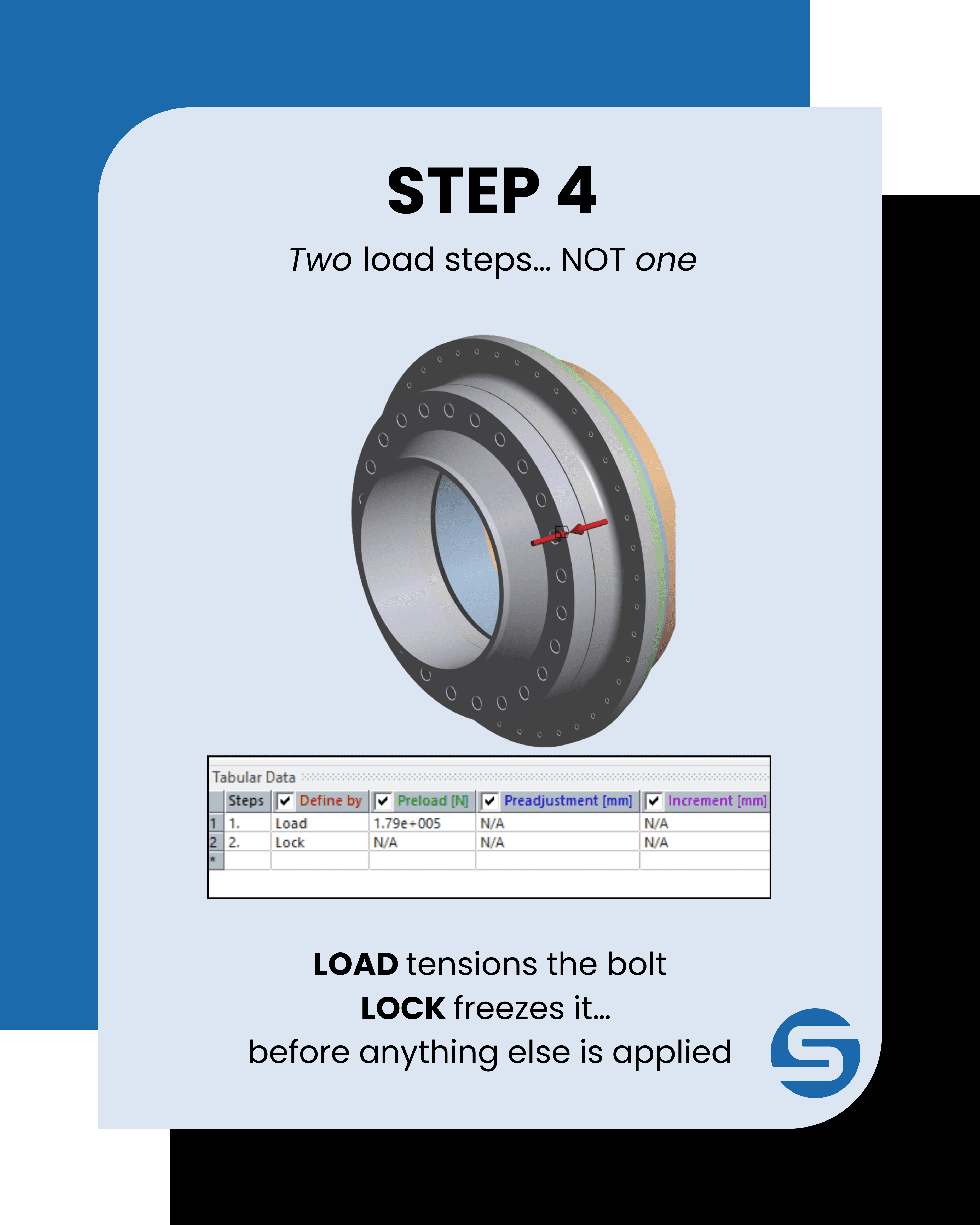
- Preload only (Define By = Load). The bolt tensions, the faces clamp, and the model reaches equilibrium with no external load applied.
- Preload locked (Define By = Lock). The bolt length is frozen at its Step 1 state, converting the preload from a prescribed load to a prescribed displacement, and external loads are applied on top.
Applied in a single step, the solver sees preload and external load simultaneously, which is not how the joint is built or loaded, and the results are not representative.
Two-step pretension table on the bolt beam — Step 1 defined by Load (1.79e+005 N), Step 2 defined by Lock
Step 5: Frictionless contact at the flange interface
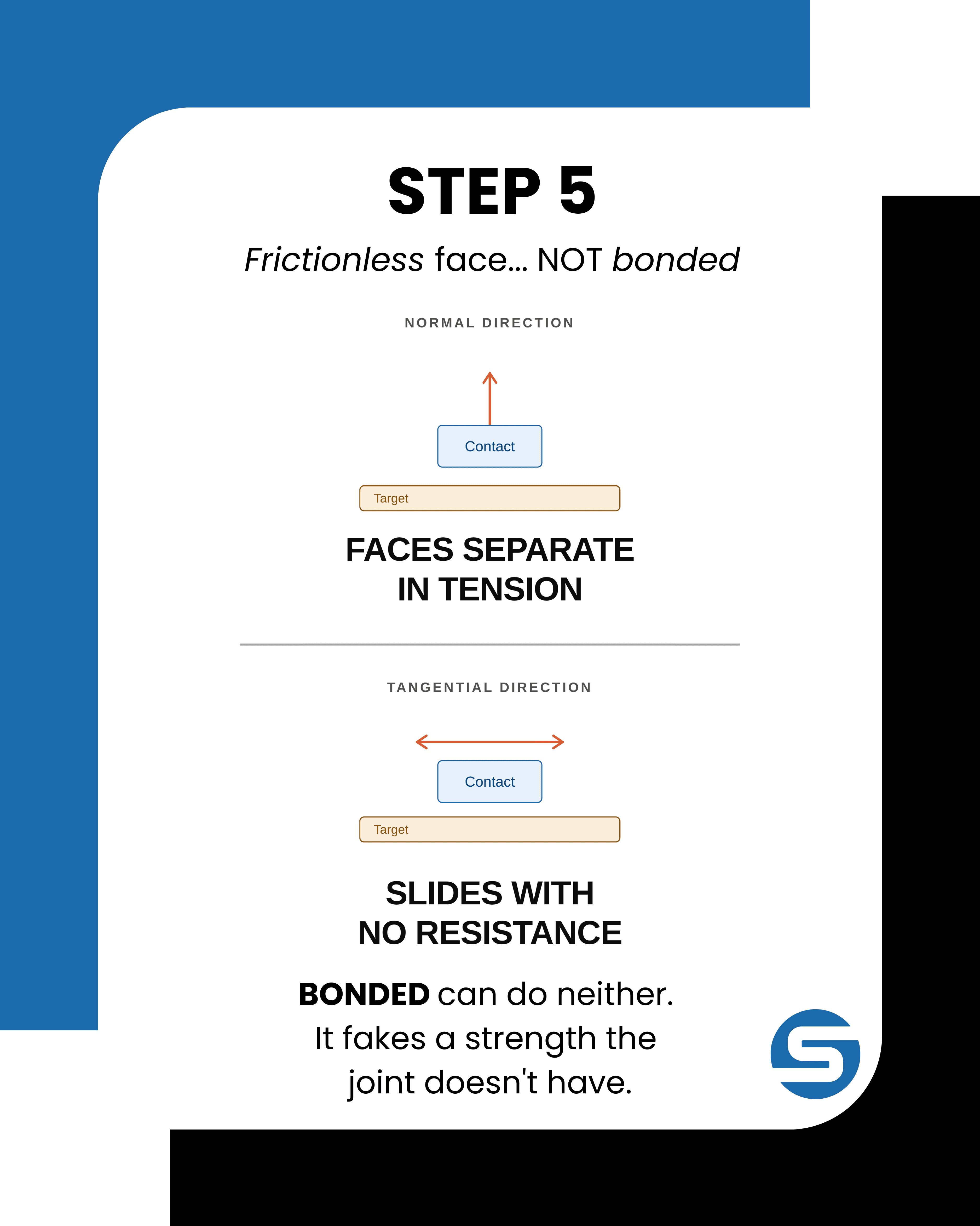
Flange face contact should be frictionless, not bonded, and this single setting determines whether the load path through the joint is physical.
Bonded contact ties the nodes together permanently. The faces cannot separate or slide, so in tension the interface itself carries tensile load straight across the joint. Real flanges can only push against each other, they cannot pull.
Frictionless contact allows separation when the interface goes into tension, so tension across the joint has to be carried by the bolts, and allows compression where the faces remain closed. That loads the bolts correctly under combined loading and captures partial or full face separation once external load overcomes the preload.
The tangential direction is a judgement call tied to the goal of the assessment. Frictionless carries no shear across the faces, so any in-plane shear passes through the bolts in bearing. That is the conservative choice when the bolt connection is the object of interest, since nothing relieves the bolts. If the joint is instead meant to resist shear by friction, frictionless cannot show that it stays put, and either a rough contact backed by a hand calculation on the available friction, or a frictional contact with a realistic coefficient, is the more representative model. A dedicated shear feature such as a spigot or fitted bolts provides a separate path again, so the assumption behind each model is worth stating.
Summary
| Step | Key decision | Why it matters |
|---|---|---|
| Geometry prep | Imprint washer faces, fill non-critical features | Gives the beam a face to scope to, keeps the mesh clean |
| Named selections | Rule-based, filtered by area | Scales to large bolt groups, reproducible and auditable |
| Remote points | Rigid at threaded end, Deformable at washer face | Wrong choice stiffens the flange and moves the stress |
| Object Generator | Correct scoping, correct template instance | Replicates a good setup, or a bad one, across the group |
| Pretension | Two steps, Load then Lock | Correct sequencing of preload and external load |
| Flange contact | Frictionless, not bonded | Bolts carry tension, faces carry compression |
Where this comes up in practice
Since real geometry solid bolts cost more, it's self explanatory that the only time you would pay that cost is when the bolt itself is what you're trying to study in detail. Therefore in whole assemblies with n bolts it's a common practice to model them as beams (cheaper, faster and good enough for the overall behaviour).
Now just cause the bolt is "dumbed down" to a beam doesn't mean the beam element isn't dumbed-down to the point of now being unrealistic. The only real cost is that we can't find how stress is actually distributed across the cross-section at specific stress-concentration points, but we weren't looking to solve for that anyway.
Then the preload, which itself is usually calculated from:
- The bolt's proof load - so we state that we want to use X% of the bolt's proof load, OR
- From a specific installation torque, converted into a clamping force.
Whichever method you use depends on the standard or project specs governing the design.
And then the Frictionless contact between flange faces doesn't matter much because shear load is carried by the bolts bearing in their holes, not by face friction anyway, so frictional contact is only needed for slip-critical joints, and that costs more to solve.
Frequently Asked Questions
Should I model every bolt as a solid body for a whole flange assembly?
No. Unless the bolt itself is what you're trying to study in detail, the common practice is to use beam elements instead.
What is bolt pretension?
Ever torqued a bolt down? If you think about it, you're not just simply spinning it, you're actually elongating it a tiny amount, to a point that it wants to spring back, which is exactly what clamps parts together, otherwise it would just re-twist right back out. That tension... is bolt pretension.
Why can't flange faces just be bonded together instead of frictionless?
Because real flanges can only push against each other, they can't pull.