Creep in High-Temperature Alloys
Here's how engineers deal with metals slowly deforming under constant loads and heat even when the stresses are below yield.

Martin Reynolds
Strategy Director | Engineer
What you will learn
- Understand the mechanism of time-dependent deformation at elevated temperatures
- Know why yield strength alone is inadequate for high-temperature design
- Select appropriate creep-resistant alloys for service conditions
- Apply design and inspection strategies to manage creep life
Prerequisites
- Basic understanding of material properties
- Familiarity with stress and strain concepts
What is Creep?
Creep is when metal slowly stretches and sags under a constant load and heat, even when the load itself is well within what the material is actually expected to handle.
When held under a constant load at elevated temperatures, a material’s atoms gradually move around and rearrange, causing the component to either stretch, sag, or thin out over time, even if the applied stresses sit comfortably below yield strength.
And if you leave it unchecked, that slow deformation ends in rupture.


Why Do Metals Creep at High Temperature?
It’s not really about how much load a component is under.
It's about how much of a material's melting point it's sitting at.
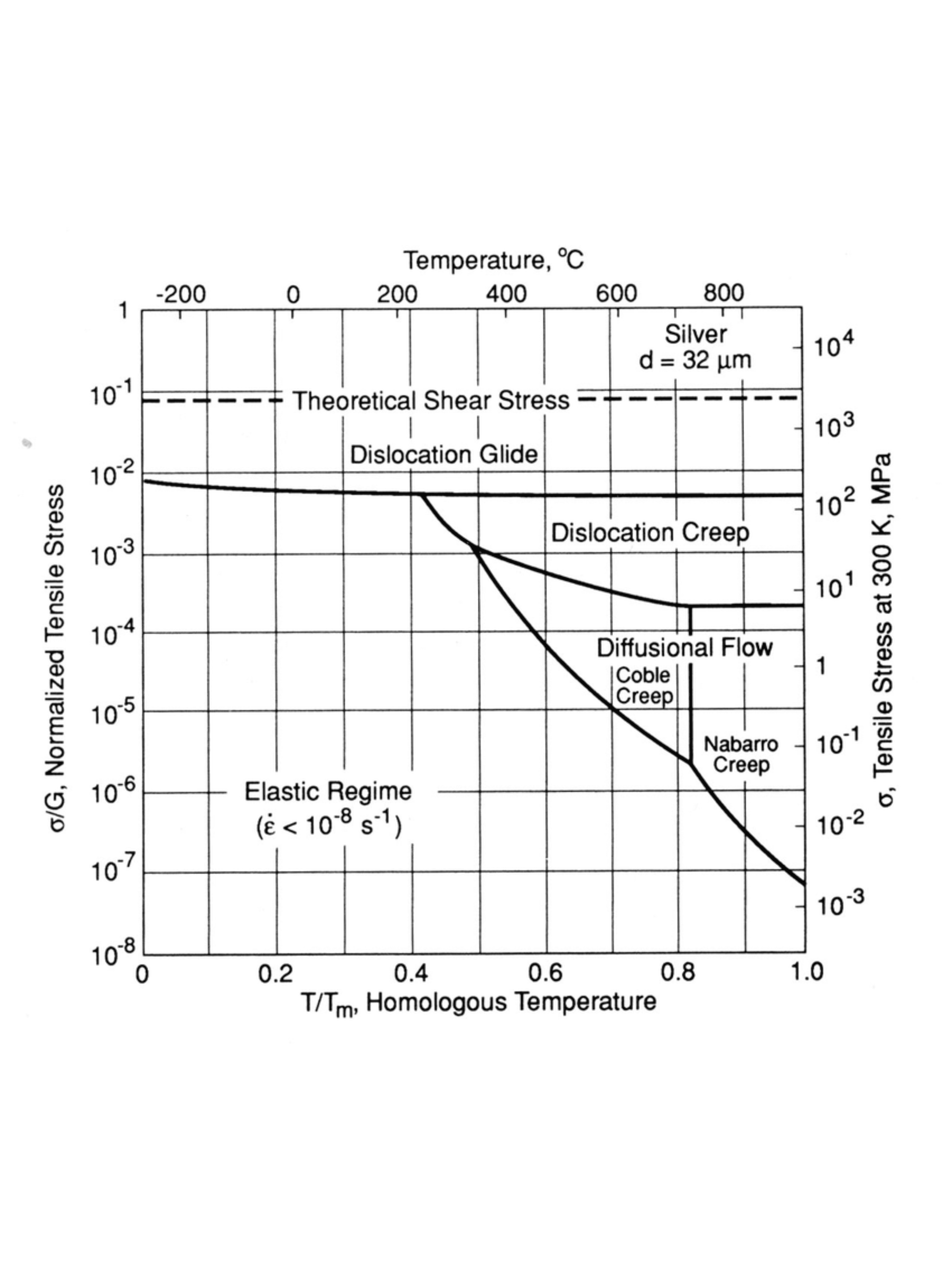
That's the actual reason creep shows up in gas turbines and boiler tubing rather than a garden gate hinge, it's a function of how close the metal is running to its own melting point, not how weak it is.
Above that threshold, two competing mechanisms drive the deformation:
- Dislocation climb and glide (power-law creep)
Think of the metal's structure as full of tiny line-shaped flaws… or dislocations. These are what actually let metal bend instead of just snap. And under high stress, these flaws hit obstacles, and so atoms nearby shuffle around just enough to help them climb right over. That's how the metal keeps on slowly but surely deforming. - Diffusion and grain boundary sliding
Under lower stress but higher heat, it's a lot quieter process. Atoms just drift along the boundaries, and those grains themselves slowly slide past one another. This slow drifting is what leaves behind those tiny voids that inspectors typically find later when they check for damage.
Now which of these 2 dominates in a given part?
It depends on where it sits on the stress vs. temperature map, which is also why the same alloy can behave completely differently at two different points in its own service envelope.
This is what's actually happening across the three creep stages.
Primary creep is the material's initial hardening response as dislocations pile up and obstruct each other, so the strain rate slows.
Secondary (steady-state) creep is the long middle phase, where hardening and recovery roughly balance and the strain rate holds close to constant - this is the number engineers actually end up designing against.
Tertiary creep is when accumulated internal damage - voids, cracks, local thinning - has reduced the effective load-bearing area enough that the strain rate accelerates toward rupture.
Known Failures:
What Creep Has Taught High-Temp Engineering
| Case | What Happened & What it Taught Us |
|---|---|
| Mohave Power Station, 1985 | A steam pipe at a US power plant burst during completely normal operation, blasting scalding steam through a door into the control room. The pipe didn't fail in the metal itself - it failed right at the weld. The original design had simply overestimated how much heat and stress that weld could handle, and the plant had been quietly running hotter than it was designed for, which wears out metal way faster than people realize. This became the textbook case for a now well-known failure type: welds cracking before the metal around them does. It's exactly why high-heat welds today need their own safety margin - not just whatever margin the base metal has. One number that says it all: six people never made it home from what should've been a routine day at the plant. |
| Nimonic 80A turbine blade, 20,000 hours | A turbine blade in an industrial gas turbine cracked from creep damage after 20,000 hours of high-heat running. Hardness tests along the blade told the real story: it was noticeably weaker at the hot end than the cooler end - proof the damage tracked how hot each part actually got, not what the original design assumption. The real cause: the alloy's internal structure - the microscopic stuff giving it strength - had quietly broken down under sustained heat. A basic strength check would never have caught this. It's exactly why heat-resistant alloys get tested over long stretches of time, not just a quick one-off strength test. |
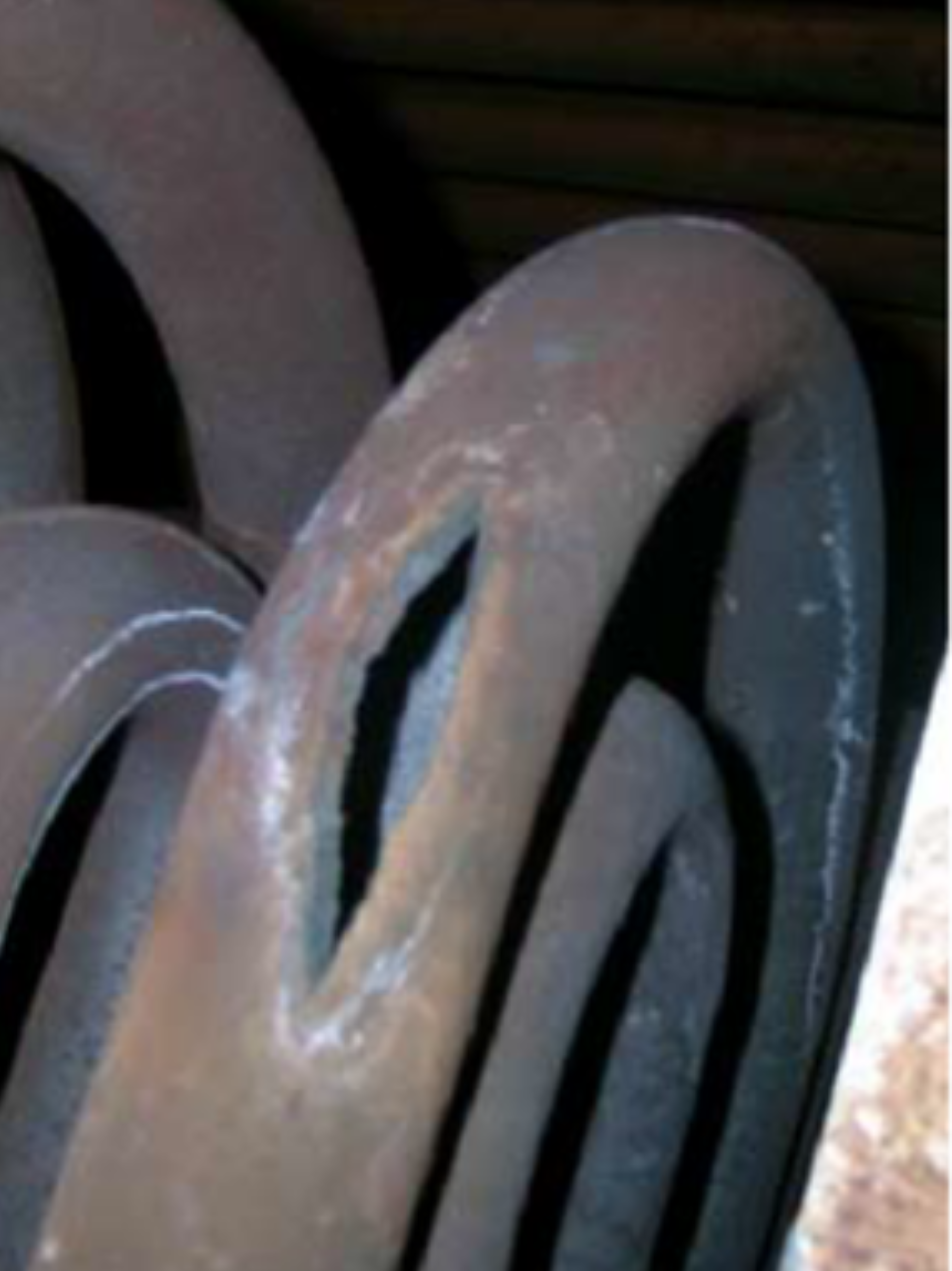
| Superheater and reheater tubes, ongoing | Boiler tubes are where creep shows up most in everyday plant life - and it's a bigger problem than most people realize. A huge chunk of power-plant breakdowns trace back to exactly this: tubes slowly weakening from heat until they just give out. One real case: a steam tube designed to run at a certain temperature had quietly been running hotter than that for years. Nothing dramatic, no overload, no alarm bells - just a steady, sustained temperature creep past what the design ever accounted for. Eventually, it ruptured at a bend. This is the quiet version of the same story Mohave and the turbine blade tell in dramatic fashion: it's rarely one big shock that causes the failure. It's a component running just a little too hot, for just a little too long. One number worth remembering: nearly a third of all boiler tube failures come down to this exact thing. |
So Then How Do You Manage It?
| Approach | Why it works |
|---|---|
| Choose creep-resistant alloys (Cr-Mo steels, nickel superalloys) | Selected specifically to resist slow deformation at temperature |
| Reduce operating stress through design | Lower stress concentrations slow the rate of creep directly |
| Control service temperatures | Creep rate is extremely sensitive to temperature, so staying within the assumptions matters |
| Inspect regularly | Early creep is detectable well before rupture occurs |
By the time creep is visible to the eye, the component has probably been deforming for a long time already.
Detecting Creep in a Structure Already in Service
All that we discussed above is about choosing materials and setting limits at the design stage.
But most of what really ends up happening and needs checking today isn't new equipment. It's stuff that's been in service for years, sometimes decades and just quietly running closer to its creep limit than anyone originally intended.
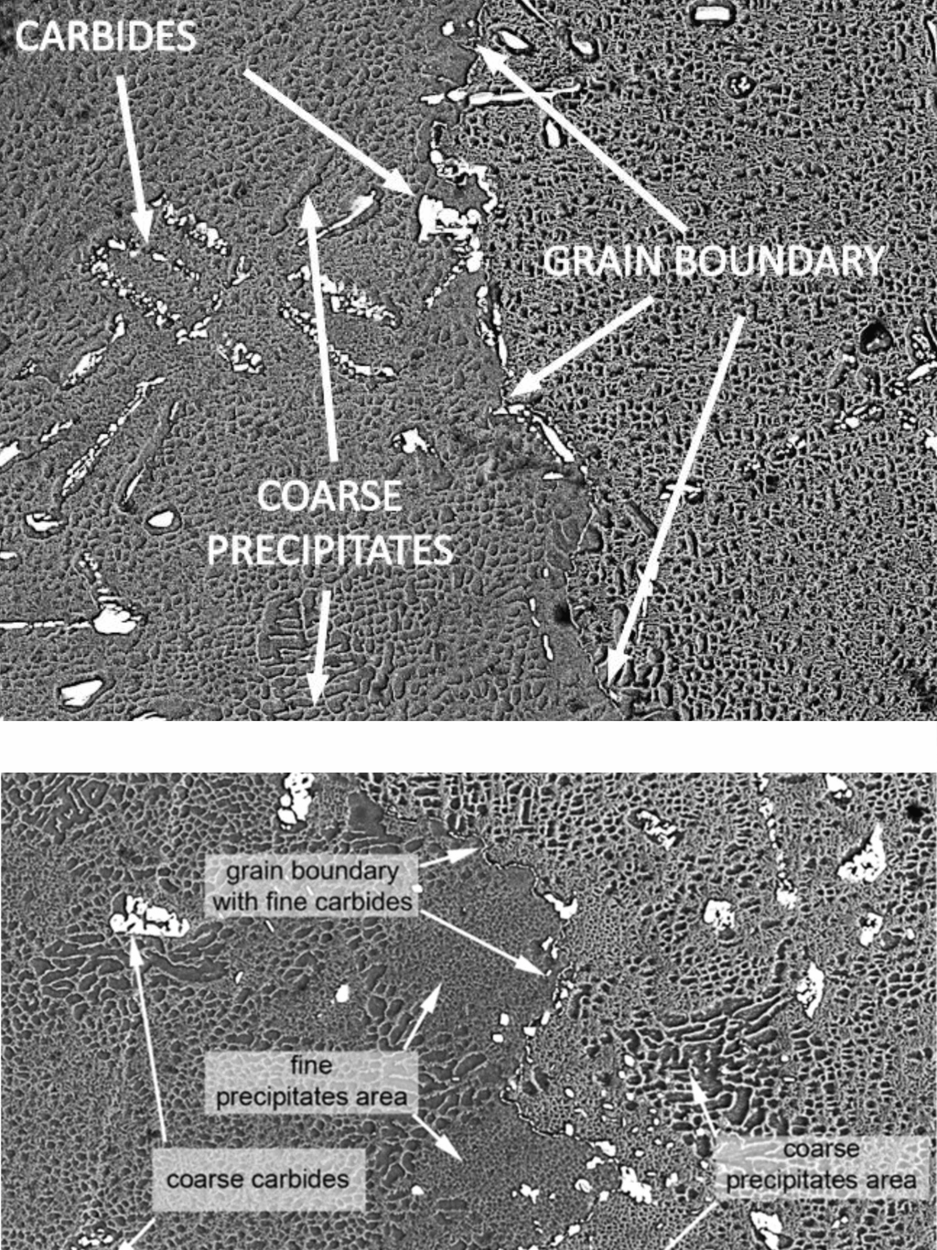
- Replica metallography (to ASTM E1351) takes a non-destructive impression of the surface microstructure in place, without cutting a sample from the component. It's the standard way to check for grain-boundary cavitation - the microscopic voids that mark early-stage creep damage - long before it's visible to the eye or shows up as a dimensional change.
- Dimensional and bulge surveys track creep strain directly, comparing current diameter or wall profile against baseline or design measurements. Small, localised bulging on a boiler tube is often the first physical sign of advancing creep.
- Oxide scale thickness measurement gives a proxy for a component's actual thermal history. Where logged operating temperatures are incomplete or unreliable - common on older assets - the accumulated oxide layer on a tube's inner surface can reveal it's been running hotter than the design ever assumed.
- Hardness testing picks up microstructural softening associated with long-term creep exposure, usually run alongside replication to cross-check findings.
- A fitness-for-service assessment to API 579-1/ASME FFS-1 pulls all of the above into a formal remaining-life estimate rather than a pass/fail result - the same logic Subco applies to structural assessments on ageing crane and pipeline assets.
Frequently Asked Questions
Can creep happen at room temperature?
Generally no. Creep only becomes significant at a fraction of a material's melting point, which for most structural steels means elevated service temperatures.
Is creep the same as fatigue?
No. Fatigue comes from repeated loading cycles, whereas creep comes from constant loads held over time at high temperature. They can occur together but are different mechanisms.
How do you know if a part is at risk of creep?
Compare its service temperature and stress against the material's creep data. Every alloy has a threshold below which creep is not a practical concern.
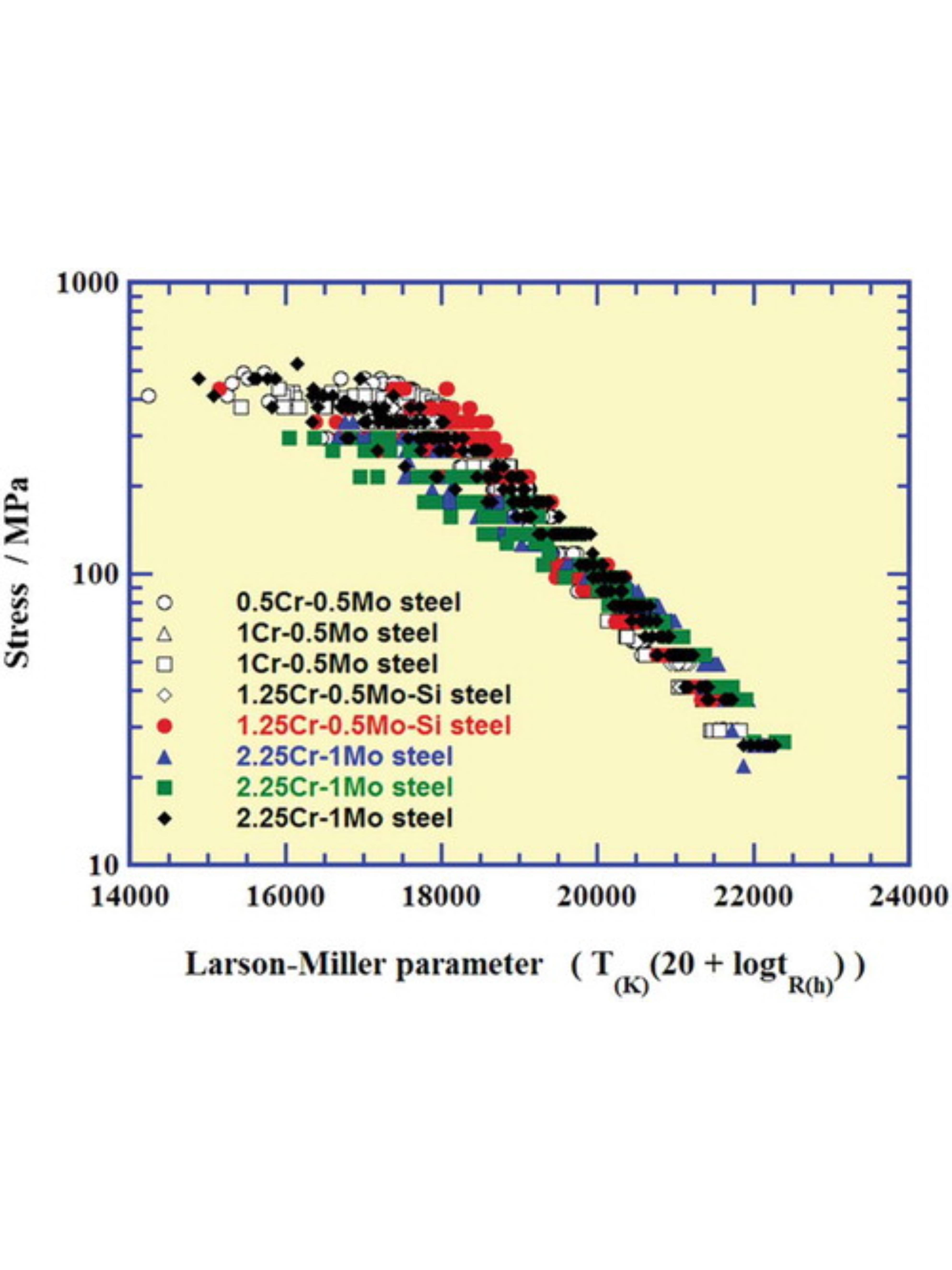
What is the Larson-Miller parameter?
It's a way of combining stress-rupture test time and temperature into a single number, so short high-temperature lab tests can be extrapolated into long-term predictions at the temperature a component will actually see in service. It's the standard tool for predicting rupture life without running a creep test for the 30 or 40 years a real component might be in service.
What's the difference between primary, secondary and tertiary creep?
Primary creep is the material hardening and slowing down early on. Secondary creep is the long steady-state phase engineers actually design against. Tertiary creep is the final, accelerating phase, where internal damage has built up enough that failure follows soon after. A component in tertiary creep is much closer to the end of its life than the start.
Can creep be arrested once it starts, or is it always progressive?
Progressive, but not necessarily urgent. Caught early through inspection, a component showing early-stage creep cavitation can often be de-rated, monitored on a shortened inspection interval, or scheduled for planned replacement rather than pulled from service immediately. What can't happen is reversing the damage itself.
Does creep affect all metals equally?
No, it's alloy-specific. Nickel superalloys and Cr-Mo steels are selected specifically because their microstructure resists dislocation movement and grain boundary sliding at high temperature. A mild steel component at the same absolute temperature as a jet engine blade would creep far faster, because it's sitting at a much higher fraction of its own melting point.
Is creep a concern for offshore or subsea structures specifically?
Less directly than for cold-climate steel, since most offshore structural steelwork runs at ambient sea temperature, well below the range where creep matters. It becomes relevant on high-temperature process equipment onboard — compressors, turbine-driven generators, exhaust systems — rather than on the platform or vessel's structural steel itself.
How is creep risk detected on a structure already built, rather than at the design stage?
Through replica metallography, dimensional surveys, and a fitness-for-service assessment against API 579-1/ASME FFS-1 — the same logic used for ageing crane and pipeline assessments, just built around a different damage mechanism.