Neuber's Rule for Notch Stress Correction
Why linear elastic FEA overstates stresses at notches, and how Neuber's Rule gives engineers a realistic picture of local elastic-plastic behaviour at stress raisers.

Martin Reynolds
Strategy Director | Engineer
What you will learn
- Understand why linear elastic FEA overpredicts notch stresses
- Apply Neuber's Rule to correct elastic stress concentrations for plasticity
- Judge whether local plasticity at a notch is tolerable for fatigue life
- Design out stress concentrations before analysis is needed
Prerequisites
- Understanding of stress and strain concepts
- Basic familiarity with finite element analysis
- Knowledge of fatigue design principles
What is Neuber’s Rule?
Neuber's Rule is a way to check how metals would behave at a sharp corner or notch, where standard stress calculations tend to make things look a lot worse than they really are.
Linear elastic FEA has a habit of overstating stress at notches, fillets, and other stress raisers. Neuber's Rule links the nominal stress and strain to what's actually happening at the notch, giving a far more realistic picture than a purely elastic model ever could.
Skip it, and you're left choosing between two costly mistakes:
- Missing real notch plasticity, which leads to fatigue failure.
- Over designing and rejecting perfectly good parts based on stress numbers that were never going to happen in real life.
Why Does Linear Elastic FEA Get Notch Stress Wrong?
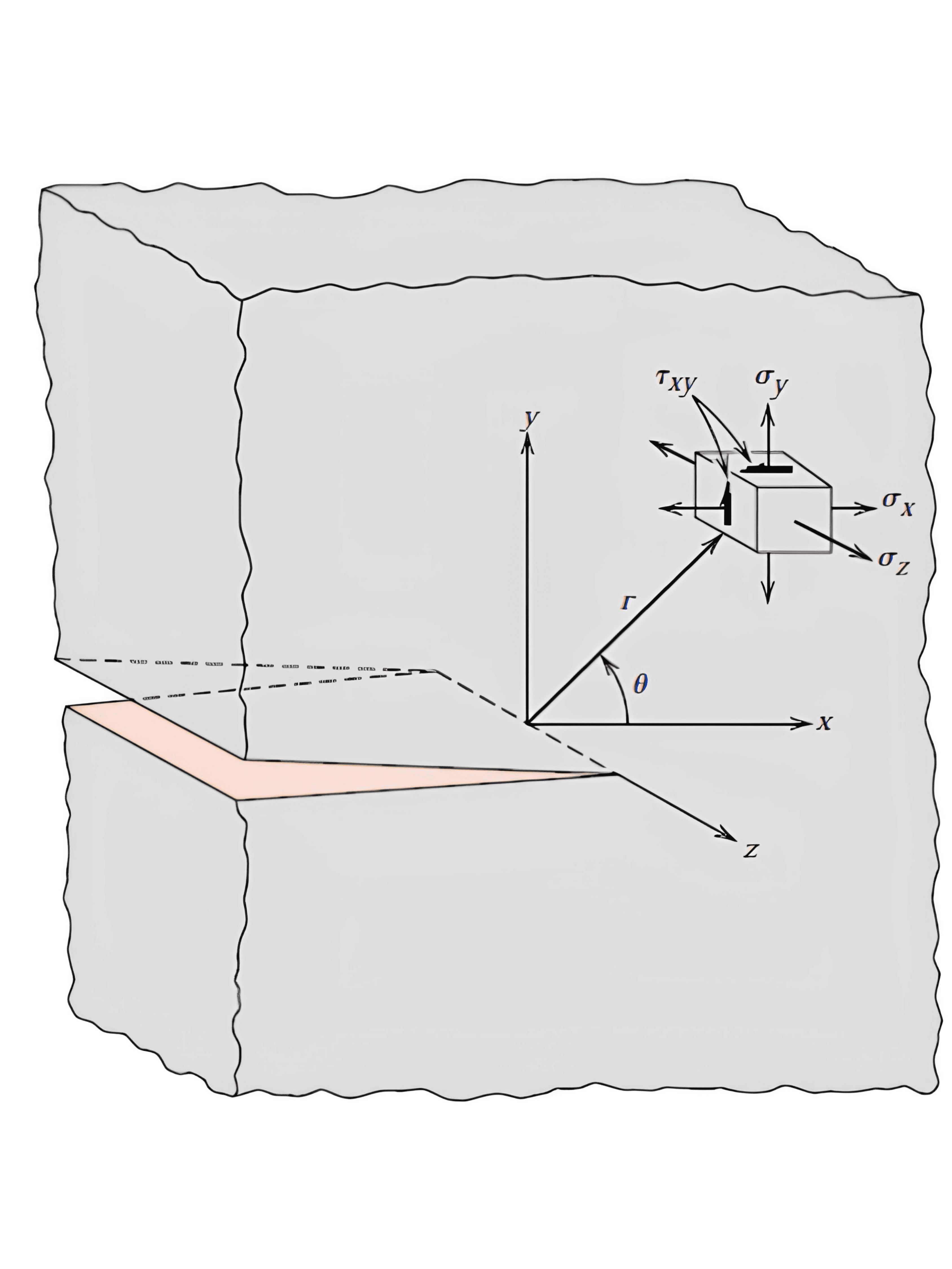
A linear elastic FEA model assumes the material can carry however much stress the geometry demands, forever, with no limit. At a sharp notch or fillet, geometry alone can multiply the nominal stress several times over. That multiplier is the theoretical stress concentration factor, Kt, and it's a purely geometric number that has nothing to do with what the material can actually withstand.
Real steel doesn't work that way. Once local stress at the notch root hits yield, the material starts deforming plastically in a small zone right at the stress raiser. That local yielding does two things an elastic model just can't see. It caps how high the actual stress can climb, and it pushes the strain the elastic model missed into that same small zone instead. The elastic FEA result ends up wrong about how the load is actually shared between stress and strain once part of the material has gone plastic.
Neuber's Rule is the correction for exactly that gap. It rests on one governing relationship:
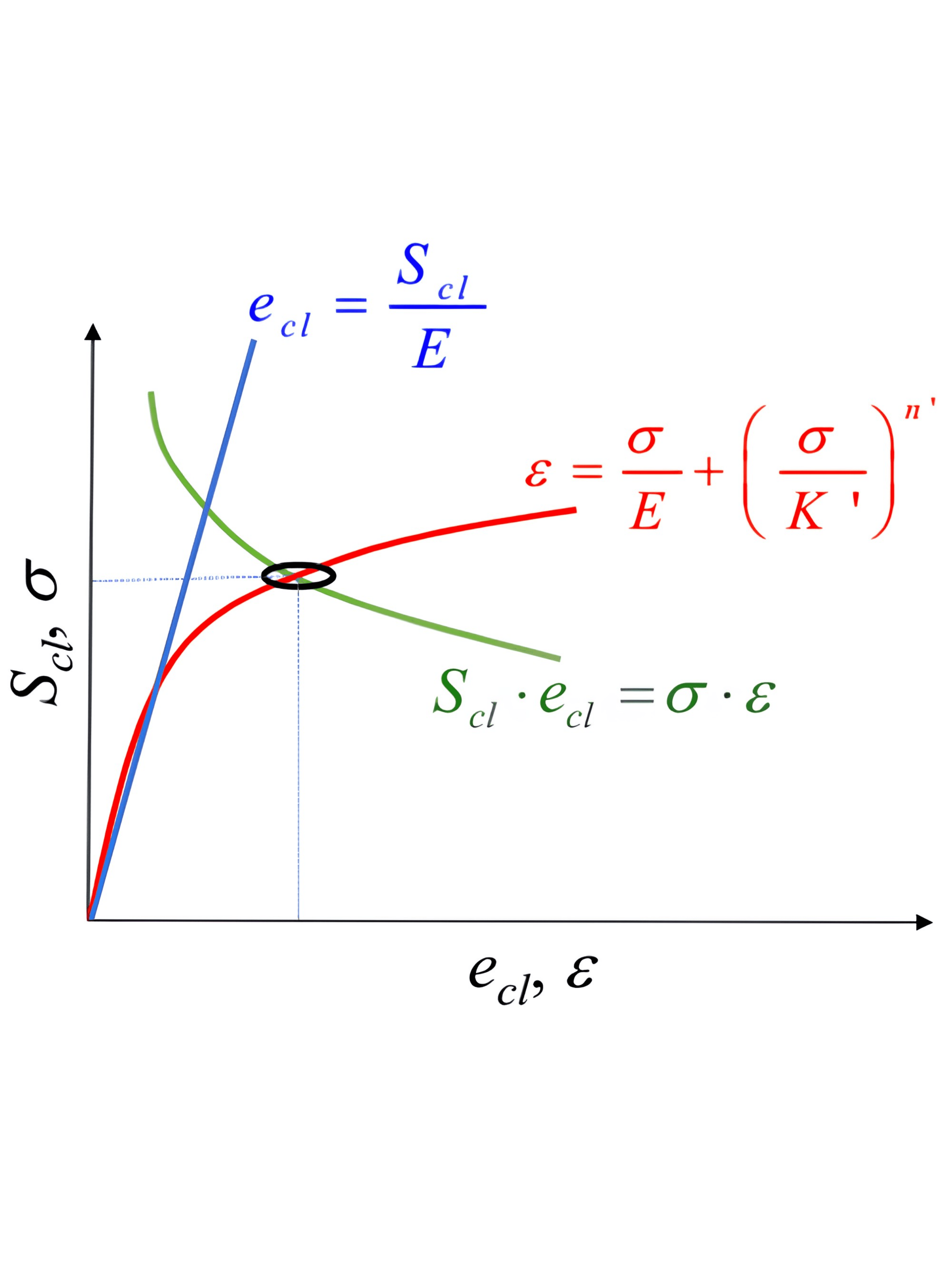
σ(local) × ε(local) = Kt² × σ(nominal) × ε(nominal)
The product of local stress and local strain at the notch is assumed to equal the elastically predicted product, scaled by Kt squared. Plot that on a stress strain axis and the fixed product forms a hyperbola, known as the Neuber hyperbola. Wherever that hyperbola crosses the material's actual stress strain curve, that's the corrected local stress and strain. Lower stress than the raw elastic FEA number, higher strain than the raw elastic FEA number, and most importantly, both numbers the material can genuinely sustain rather than one the elastic model just invented.
Neuber's Rule isn't the only way to do this correction.
Glinka's Equivalent Strain Energy Density (ESED) method solves the same problem a different way. Instead of matching the stress strain product, it matches the strain energy density, the elastically predicted energy against the real energy under the material's actual curve. The practical difference matters. Neuber's Rule tends to run conservative, meaning it over predicts local stress, under plane strain, the high constraint condition typical of thick sections and deep notches. Glinka's method tracks closer to reality there. Under plane stress, thin sections and shallow notches, the two methods converge closely, and Neuber's Rule is the simpler, faster tool to reach for.
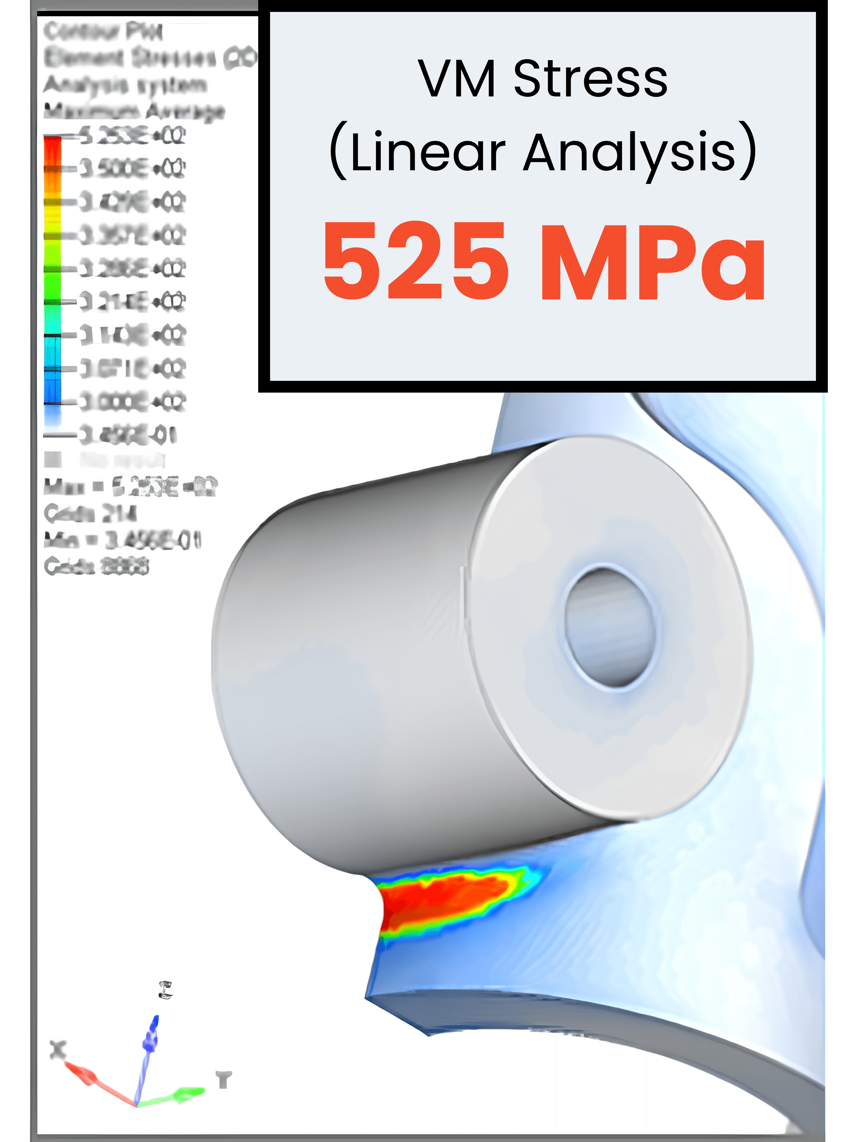
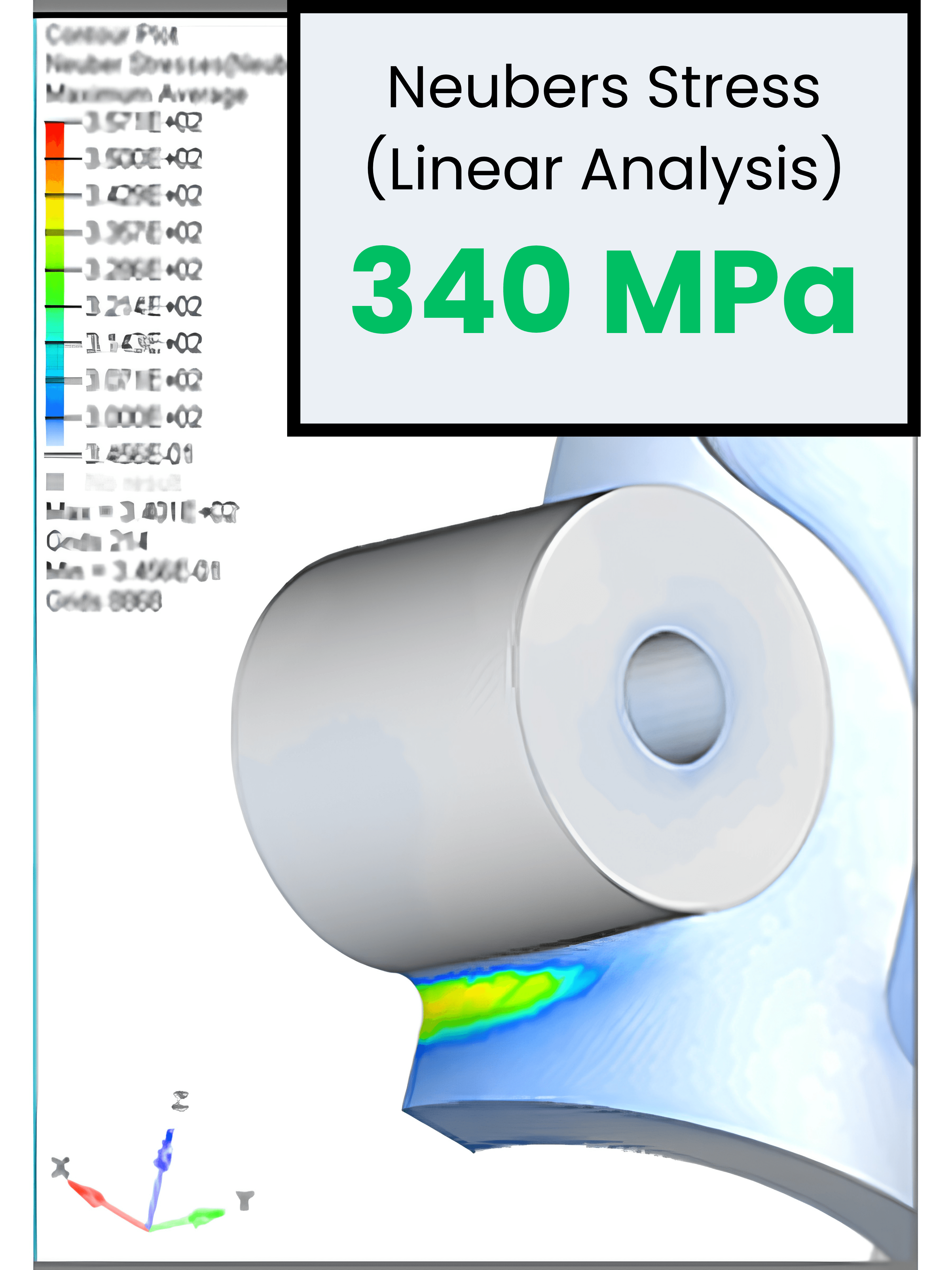
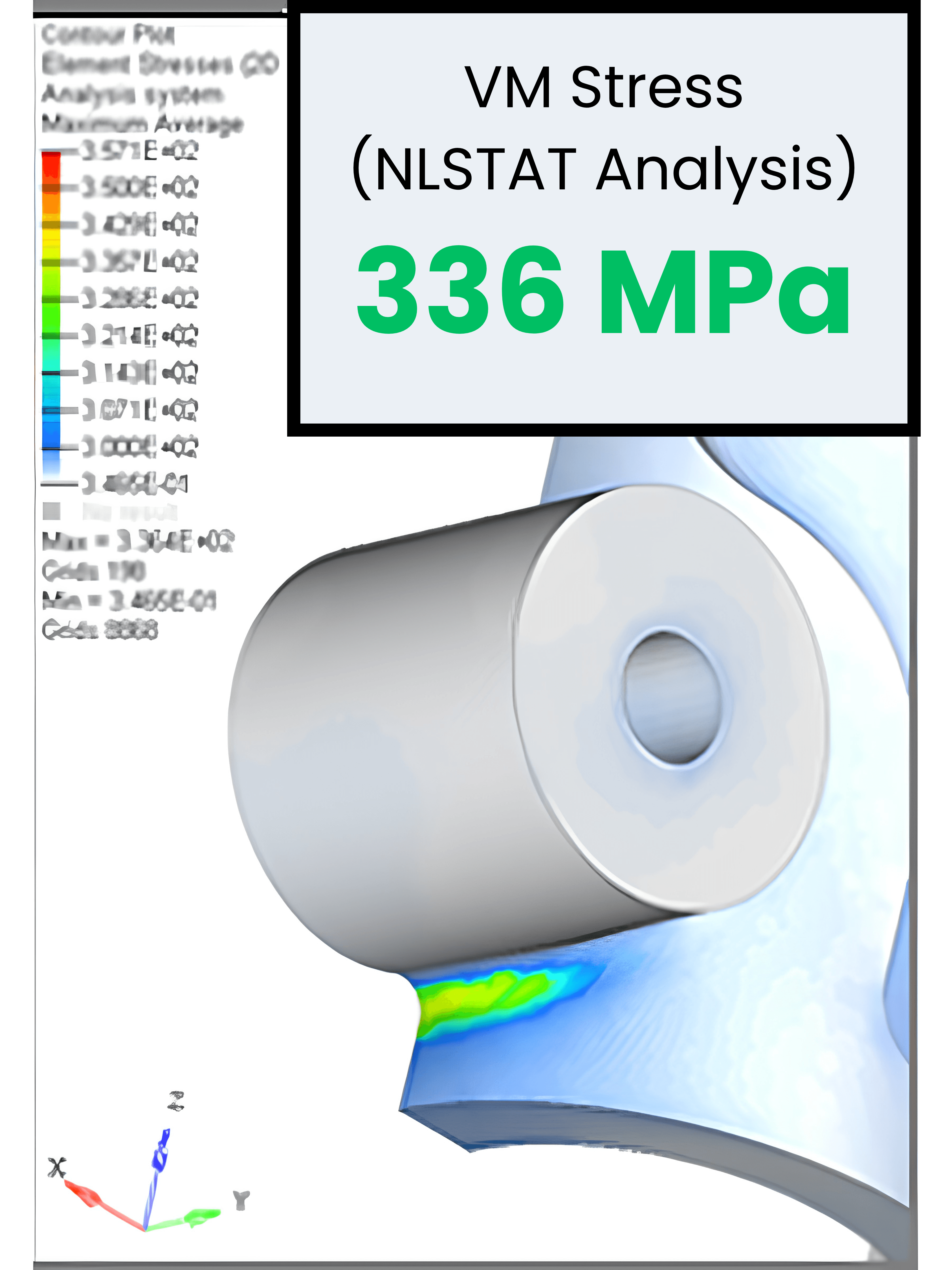
Your linear FEA said 525 MPa…
It was wrong by 185
Known Failures: What Notch Stress Has Taught Fatigue Design
| Case | What happened & What it taught us |
|---|---|
| De Havilland Comet, 1954 | The world's first commercial jet airliner suffered two catastrophic in flight break ups within three months of each other, killing 56 people. Investigators traced both back to fatigue cracks starting at the sharp corners of the aircraft's near square window and hatch cutouts, stress concentrations far higher than de Havilland's engineers had ever accounted for, repeatedly loaded by the pressurisation and depressurisation cycle of every single flight. A full scale fuselage tested in a water tank eventually failed at its own window corner after thousands of pressure cycles, confirming the mechanism. The fix that followed, rounded windows, mandatory fatigue testing for pressurised fuselages, and design standards that persist industry wide today, exists because the Comet made the cost of an unquantified stress concentration impossible to ignore. |
| Aloha Airlines Flight 243, 1988 | Thirty four years after the Comet, the same underlying mechanism showed up again, just in a different form. An 18 foot section of fuselage tore away from a Boeing 737 at 24,000 feet, the result of fatigue cracks growing simultaneously from thousands of rivet holes along a single lap joint. Each hole held its own small stress concentration, individually tolerable, but collectively catastrophic once enough of them linked up. The aircraft had flown nearly 90,000 pressurisation cycles in a corrosive coastal environment, and the corroded joint had let stress concentrate at those rivet holes far more than the original design ever assumed. Unlike the Comet, the geometry wasn't the surprise this time. The mechanism was already well understood by 1988. What failed was spotting how far the real stress state had drifted from the design assumption over decades of service, which is exactly the gap a nominal elastic stress calculation would miss. |
| Shaft and crankshaft fillet fatigue, ongoing | Away from aircraft fuselages, this is where stress concentration shows up constantly in ordinary mechanical design. Any shaft, axle, or crankshaft with a change in diameter has a fillet, and that fillet is a stress raiser by definition. Fatigue failure analyses of crankshafts consistently trace crack initiation back to the crankpin web fillet or main journal fillet, commonly linked to a fillet radius that was too small, poorly finished, or under analysed for the actual stress concentration it created. In some failed crankshafts, stresses ran as low as around 175 MPa, well below the parent material's nominal fatigue strength. Fillet rolling, which induces compressive residual stress at the notch root, is now standard practice specifically to counteract this. Where the Comet and Aloha stories are dramatic single events, this is the everyday version, an unremarkable looking radius, quietly running closer to a nominal stress calculation would suggest. |
How do you apply it?
| Approach | Why it works |
|---|---|
| Apply Neuber's Rule at notches and stress raisers | Judges whether local plasticity is actually tolerable within an otherwise elastic component |
| Use generous radii and smooth transitions | Reduces the problem at the design stage, before any analysis is even needed |
| Validate with FEA on fatigue-sensitive parts | Confirms the corrected stress picture holds up under real loading |
The process is a correction, not a substitute for good detailing.
The best notch will always be the one that was properly designed out in the first place.
Frequently Asked Questions
Why does linear elastic FEA overestimate stress at notches?
Because it assumes the material stays perfectly elastic everywhere, when in reality small areas of local plasticity relax that peak stress.
Does Neuber's Rule replace the need for FEA?
No, they work together. Neuber's Rule is particularly useful to sanity-check notch stress results on sensitive components.
What happens if notch plasticity is ignored in a fatigue design?
The part would probably fail from repeated loading well before its calculated fatigue life, because the actual local stress behaviour was never accounted for.
What is the Neuber hyperbola?
It's the curve traced by holding the product of local stress and local strain constant, equal to Kt² times the nominal elastic stress-strain product. Where that curve crosses the material's actual stress-strain curve is the corrected local condition at the notch.
How does Neuber's Rule differ from Glinka's method?
Neuber's Rule matches the stress-strain product; Glinka's Equivalent Strain Energy Density method matches the strain energy density instead. They converge under plane stress, but Neuber's Rule tends to run more conservative under plane strain, where Glinka's method tracks closer to reality.
Is Neuber's Rule always conservative?
Generally, yes for plane strain conditions, which is part of why it remains the default choice for a quick, safe first-pass correction. It can be less conservative in some plane stress cases, which is why validation against test data or a second method matters on genuinely fatigue-critical parts.
Can Neuber's Rule be applied without running FEA at all?
Yes, provided a nominal stress and a theoretical stress concentration factor are available from a standard reference such as Peterson's charts. FEA becomes more valuable for complex geometries where Kt isn't available from a standard chart.
Does Neuber's Rule apply to any material, or just steel?
The relationship itself is general, but it depends entirely on having an accurate stress-strain curve for the actual material. It's most commonly applied to metals with well-characterised cyclic stress-strain behaviour, and less reliable for materials that don't follow a smooth, well-behaved curve.