Designing bolted joints
Bolted joints are common place in mechanical design, and yet the science behind what makes a good bolted connection is one of the least understood areas of design. A preloaded bolt typically sees less than a fifth of the load applied to the joint. Around 87% of the tightening torque never reaches the preload at all. And a joint can carry more external load than its total preload before it opens. Each of these runs against intuition, and each has direct consequences for how joints should be specified, installed and checked.
This article explains the behaviour behind them, following VDI 2230 Part 1 (2015).
When does a joint need a bolt calculation?
The rule of thumb: run a bolt calculation when the preload carries the load. If the joint relies on clamp force to resist slip, stay closed, seal or survive fatigue, the preload has to be designed and proven.
Calculate, or check?
Mechanical equipment: winches, A-frames, sheaves, clamps
- A sanity check is enough
- Non-structural fixings, covers and brackets
Structural joints, checked to the Eurocode
- A sanity check is enough
- Secondary steel and service routing
Cyclic or fatigue loading
- A sanity check is enough
- Catalogue joints used within the supplier's rating
Transverse load or torque carried by friction (flanges, couplings)
- A sanity check is enough
- Small bolts, typically below M8, using a standard torque table and engineering judgement
Eccentric load, prying or a risk of opening
- A sanity check is enough
Sealing and pressure joints
- A sanity check is enough
| Run a bolt calculation | A sanity check is enough |
|---|---|
| Mechanical equipment: winches, A-frames, sheaves, clamps | Non-structural fixings, covers and brackets |
| Structural joints, checked to the Eurocode | Secondary steel and service routing |
| Cyclic or fatigue loading | Catalogue joints used within the supplier's rating |
| Transverse load or torque carried by friction (flanges, couplings) | Small bolts, typically below M8, using a standard torque table and engineering judgement |
| Eccentric load, prying or a risk of opening | |
| Sealing and pressure joints |
For catalogue equipment such as a gearbox, use the supplier's bolts and installation torque, as long as the equipment is used as specified. For common structural connections, standard geometry and established guidance are usually the right answer. A detailed calculation earns its keep when the geometry or the loading falls outside what that guidance assumes.
Which standard?
Choosing a method
VDI 2230 Parts 1 and 2
- Use it for
- Highly loaded preloaded joints in machinery and equipment outside the structural codes
- Strengths
- The most complete method: stiffness, preload scatter, embedding, fatigue and torque. Widely recognised
- Limits
- Time-consuming, with many inputs. The single-bolt model needs Part 2 or FE for bolt groups
Eurocode 3 (EN 1993-1-8)
- Use it for
- Steel structures: bearing, slip-resistant and tension connections
- Strengths
- Simple, familiar hand calculations. Preload and tightening set by EN 14399 and EN 1090-2
- Limits
- Preload is set by the code, not designed for the joint. Limited treatment of eccentric load, prying and bolt fatigue
Lloyd's Register (LAME)
- Use it for
- Marine lifting appliances on LR-classed equipment: cranes, derricks, LARS
- Strengths
- A class-accepted route, with specific checks such as slewing ring bolting
- Limits
- Only relevant when LR certifies. Prescriptive, with less insight into joint behaviour
DNV (for example DNV-ST-0378, DNV-RP-C203)
- Use it for
- Offshore lifting appliances and structures under DNV certification
- Strengths
- Class-accepted, with offshore load cases, dynamic factors and bolt fatigue data
- Limits
- Rules spread across several documents, often pointing to other standards for the detailed bolt check
ASME (BPVC VIII, PCC-1)
- Use it for
- Pressure vessel flanges and their assembly
- Strengths
- Well established allowable-stress checks
- Limits
- Imperial and ASTM basis. Flange rules are for gasketed pressure joints only
| Standard | Use it for | Strengths | Limits |
|---|---|---|---|
| VDI 2230 Parts 1 and 2 | Highly loaded preloaded joints in machinery and equipment outside the structural codes | The most complete method: stiffness, preload scatter, embedding, fatigue and torque. Widely recognised | Time-consuming, with many inputs. The single-bolt model needs Part 2 or FE for bolt groups |
| Eurocode 3 (EN 1993-1-8) | Steel structures: bearing, slip-resistant and tension connections | Simple, familiar hand calculations. Preload and tightening set by EN 14399 and EN 1090-2 | Preload is set by the code, not designed for the joint. Limited treatment of eccentric load, prying and bolt fatigue |
| Lloyd's Register (LAME) | Marine lifting appliances on LR-classed equipment: cranes, derricks, LARS | A class-accepted route, with specific checks such as slewing ring bolting | Only relevant when LR certifies. Prescriptive, with less insight into joint behaviour |
| DNV (for example DNV-ST-0378, DNV-RP-C203) | Offshore lifting appliances and structures under DNV certification | Class-accepted, with offshore load cases, dynamic factors and bolt fatigue data | Rules spread across several documents, often pointing to other standards for the detailed bolt check |
| ASME (BPVC VIII, PCC-1) | Pressure vessel flanges and their assembly | Well established allowable-stress checks | Imperial and ASTM basis. Flange rules are for gasketed pressure joints only |
From system loads to a single bolt
Every bolt calculation follows the same route. Start with the load cases for the whole system. Draw a free body diagram with its boundary conditions to find the loads on the joint: three forces and three moments. Distribute those across the bolt group, whether rectangular, circular or asymmetric, to find the most highly loaded bolt. Then check that bolt on its own, as a through bolt, in a tapped hole or in an insert, which gives its utilisation and its tightening torque. VDI 2230 Part 2 covers the bolt group. Part 1, the subject of this lesson, covers the single bolt.
How a preloaded joint carries load
How preloaded joints fail
- Slip: transverse load overcomes friction in the interface.
- Opening: the interface separates, so the bolt takes the full load and seals leak.
- Self-loosening: repeated transverse slip turns the nut off.
- Fatigue fracture: usually at the first loaded thread of the nut.
A bolted joint is two springs
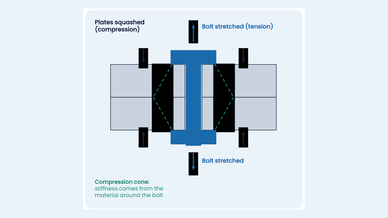
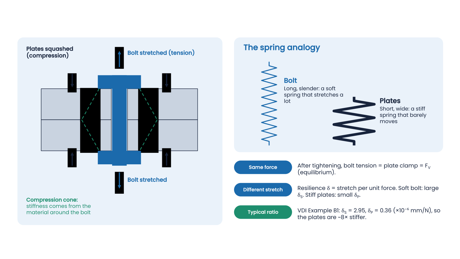
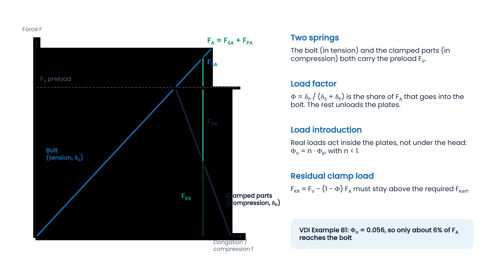
Tightening a nut stretches the bolt and squashes the plates, and both carry the same force: the preload FV. The bolt is long and slender, a soft spring that stretches a lot. The plates are short and wide, a stiff spring that barely moves. Their stiffness comes from a cone of material spreading out from under the head, shown at the top of this post.
VDI 2230 describes each part by its resilience δ, the stretch per unit force. In the guideline's worked example B1, an M12 12.9 piston rod bolt, the bolt resilience δS is 2.95 × 10⁻⁶ mm/N and the plate resilience δP is 0.36 × 10⁻⁶ mm/N, so the plates are about eight times stiffer. While the plates stay in contact, the bolt and plates must move by the same tiny amount. Because the plates are stiff, that movement releases a lot of clamp force, but because the bolt is flexible, it adds very little bolt tension.
What happens when external load is applied
Take a joint with 100 kN of preload and a load factor of 0.1. Apply a 60 kN separating load and the squashed plates spring back, giving up 54 kN of clamp. The bolt stretches only slightly more and picks up just 6 kN. That is why a preloaded bolt sees only a small part of the external load, and only a small fatigue amplitude.
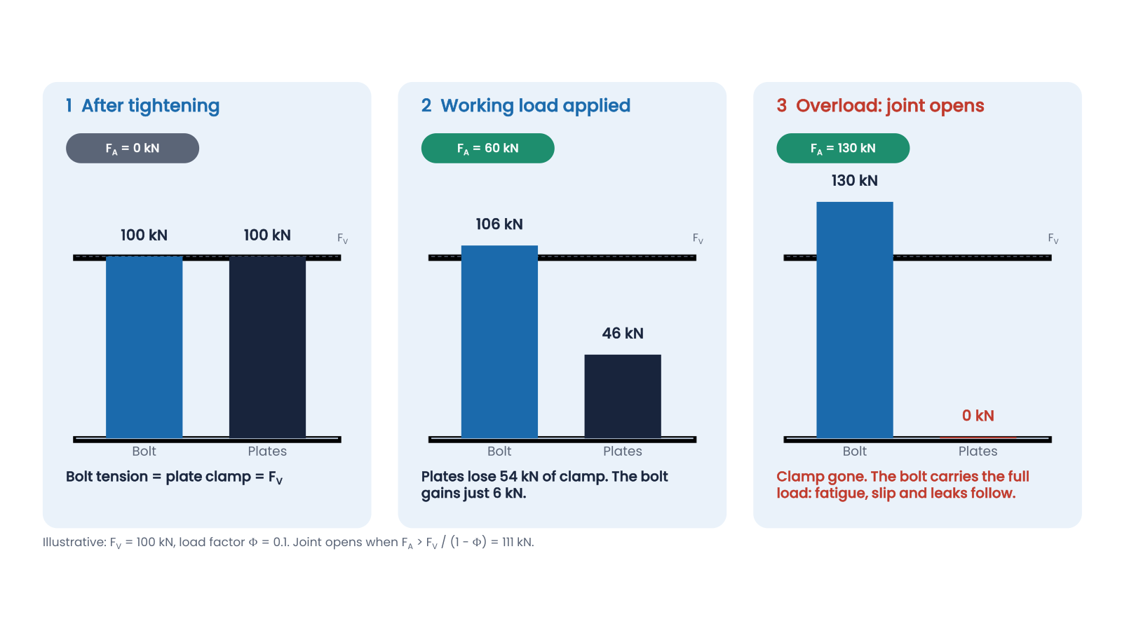
Push past FV / (1 − Φ), about 111 kN here, and the plates separate. From then on the bolt carries the whole external load, its stress amplitude jumps, and friction grip and sealing are lost.
The load factor: who takes the load
The external load FA splits between bolt and plates in proportion to their stiffness, like two springs side by side. The load factor ΦK = δP / (δS + δP) is the share that reaches the bolt, FSA = Φ·FA. The rest, FPA = (1 − Φ)·FA, unloads the plates. A soft bolt and stiff plates give a small Φ.
Where the load enters matters too. Loads rarely act right under the head. Entering nearer the interface, they bypass part of the plates, so VDI 2230 reduces the load factor with a load introduction factor n: Φn = n·ΦK, with n below 1. In Example B1, ΦK is 0.16 with the load under the head, but with n = 0.35 only about 6% of FA reaches the bolt. A soft gasket or a short, stiff bolt pushes the other way, towards half the load.
There's a trade-off. A low Φ means a small stress amplitude in the bolt, which is good for fatigue, but the plates unload more, so the joint needs enough preload to stay closed. The residual clamp load, FKR = FV − (1 − Φ)·FA, must stay above the clamp load the joint needs, FKerf, in every load case.
Worked example: does the joint open?
Ten M12 A4-80 stainless bolts clamp two 20 mm steel plates. Each bolt has a guaranteed preload of about 22 kN, 220 kN for the joint, and the load factor is 0.15. Now apply 240 kN of external tension. It pulls against only 220 kN of preload, so surely the joint separates?
It doesn't. The bolts gain 0.15 × 240 = 36 kN, rising from 220 to 256 kN, and the plates lose 0.85 × 240 = 204 kN, falling from 220 to 16 kN. Equilibrium checks it: 240 kN of external load plus 16 kN of plate push equals 256 kN of bolt tension. The joint opens at 220 / 0.85 ≈ 259 kN.
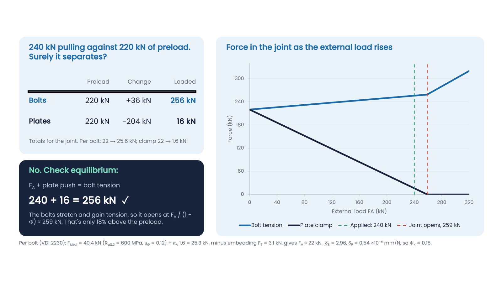
The lesson cuts both ways. The bolts stretch, gain tension and hold the joint closed beyond the preload, but only by about 18% here. Don't bank on that margin unless the assumed preload and stiffness are really achieved on site. In practice, design as if the joint opens close to the preload, and keep the residual clamp above FKerf, not just above zero.
The 22 kN comes from VDI 2230: a permissible assembly preload of 40.4 kN at 90% of the 600 MPa proof stress with a thread friction of 0.12, divided by a tightening factor of 1.6 for a calibrated torque wrench (25.3 kN), less 3.1 kN of embedding.
Why the preload you specify isn't the preload you get
Where the torque goes
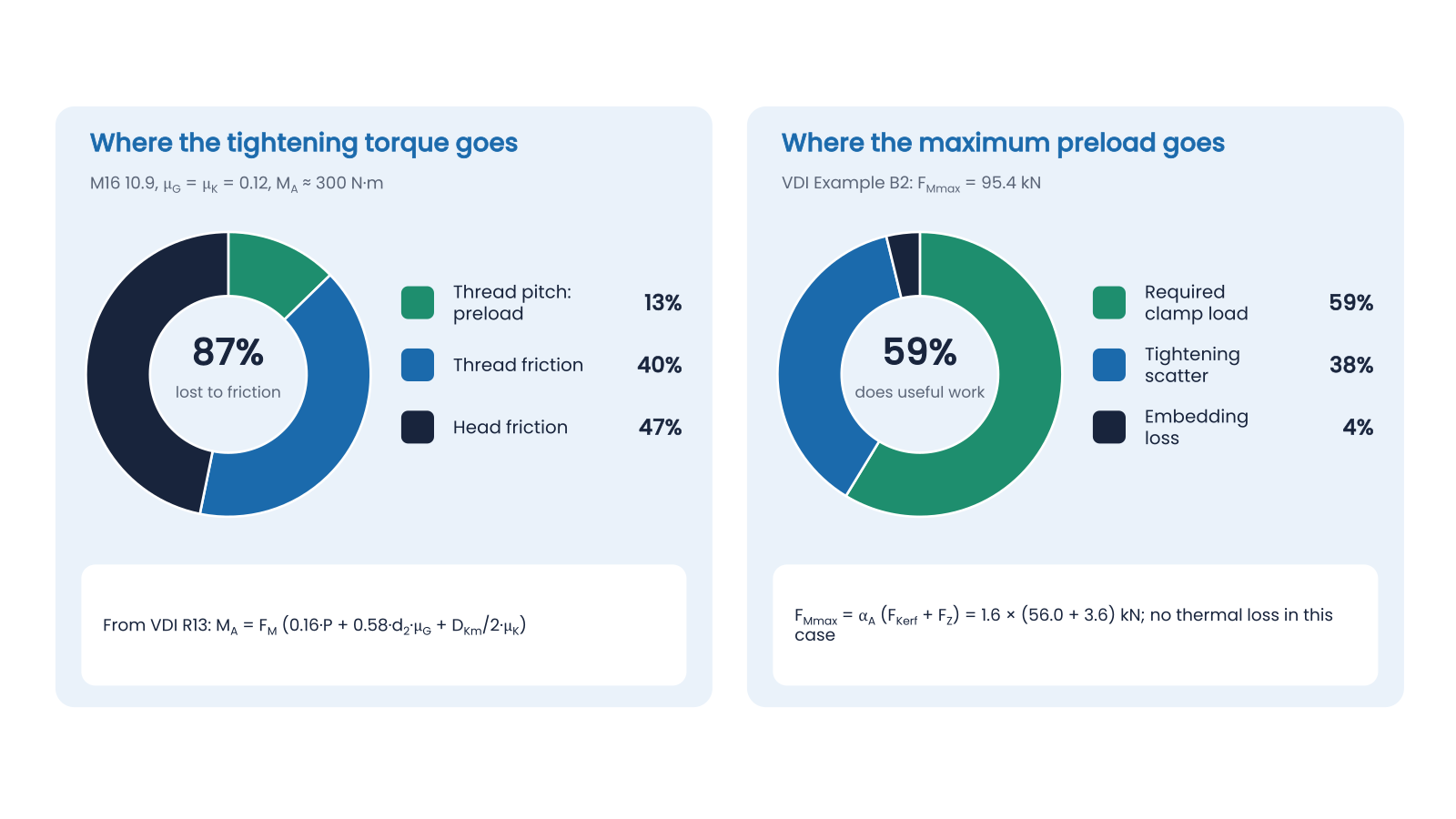
When you tighten by torque, most of the effort goes into friction. An M16 10.9 bolt with friction coefficients of 0.12 in the thread and under the head needs about 300 N·m, and only 13% of it stretches the bolt. Thread friction takes 40% and head friction 47%. A small change in friction therefore moves the preload a long way, so the friction assumed in the calculation must match the lubricant used on site, including whether it goes under the head as well as on the threads.
The preload budget is just as revealing. In VDI Example B2, a flange coupling with M16 10.9 bolts, the maximum assembly preload is 95.4 kN. Only 56 kN of that, 59%, is the clamp load the joint needs. Embedding takes 3.6 kN, 4%, and the remaining 38% is allowance for tightening scatter.
Size the bolt for the maximum, the joint for the minimum
No tightening method hits the target exactly. VDI 2230 captures the scatter in the tightening factor αA = FMmax / FMmin. The bolt has to survive the top of the scatter band, FMmax, while the joint can only rely on the bottom, FMmin. So the rule is: size the bolt for the maximum possible preload and the joint for the minimum. Target 70% of yield with 10% scatter, for example, and the bolt checks use about 77% while the clamp-force checks use about 63%.
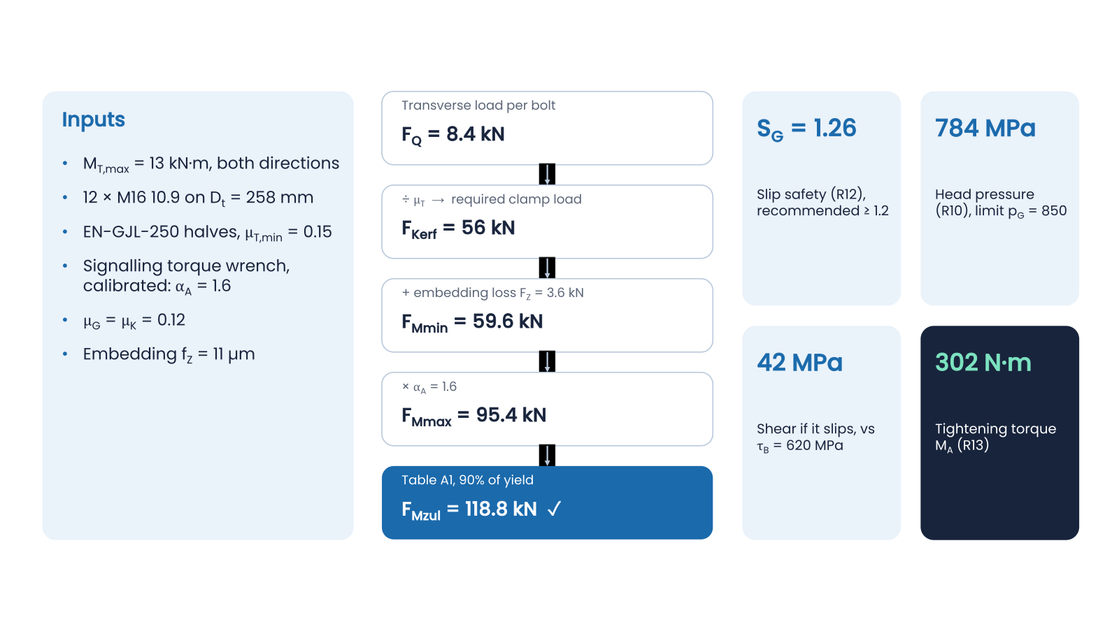
Example B2 shows how much the method matters. The joint needs FMmin = 59.6 kN and the bolt can take 118.8 kN.
Same joint, three tightening methods
Ultrasonic elongation control
- αA
- 1.2
- FMmax
- 71.6 kN
- Result
- 60% of capacity: passes
Calibrated torque wrench
- αA
- 1.6
- FMmax
- 95.4 kN
- Result
- 80% of capacity: passes
Torque wrench, friction estimated
- αA
- 2.0
- FMmax
- 119.3 kN
- Result
- Exceeds 118.8 kN: the bolt fails
| Method | αA | FMmax | Result |
|---|---|---|---|
| Ultrasonic elongation control | 1.2 | 71.6 kN | 60% of capacity: passes |
| Calibrated torque wrench | 1.6 | 95.4 kN | 80% of capacity: passes |
| Torque wrench, friction estimated | 2.0 | 119.3 kN | Exceeds 118.8 kN: the bolt fails |
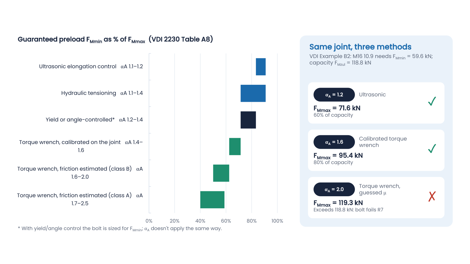
Better control costs money, but often less than a bigger bolt. Load-indicating (DTI) washers compress to a calibrated gap, with αA of about 1.1 to 1.5. Hydraulic tensioners stretch the bolt directly, at about 1.1 to 1.4, and strain-gauged bolts read their own load, at about 1.1 to 1.2, though they may need tailoring to the application.
Embedding: preload lost after tightening
Once the joint is loaded, the peaks of surface roughness keep flattening: on the thread flanks, under the head and nut, and at every interface. Only what happens after tightening costs preload, but a few microns of squash cost kilonewtons: FZ = fZ / (δS + δP). For uncoated steel with a roughness Rz of 10 to 40 µm, VDI 2230 gives guide values of 3 µm in the thread, 3 µm at each head or nut face and 2 µm at each inner interface. In Example B2, 11 µm in total costs 3.6 kN.
Hardness matters. Softer parts accept less pressure under the head, and for steels VDI 2230 suggests a limit pG of roughly three times the Brinell hardness. An M16 10.9 head at full preload presses at 784 MPa: fine on EN-GJL-250 cast iron at 850 MPa, but too much for S355 at 760 MPa or S235 at 490 MPa without a hardened washer. Exceed the limit and the material creeps under the head, even at room temperature.
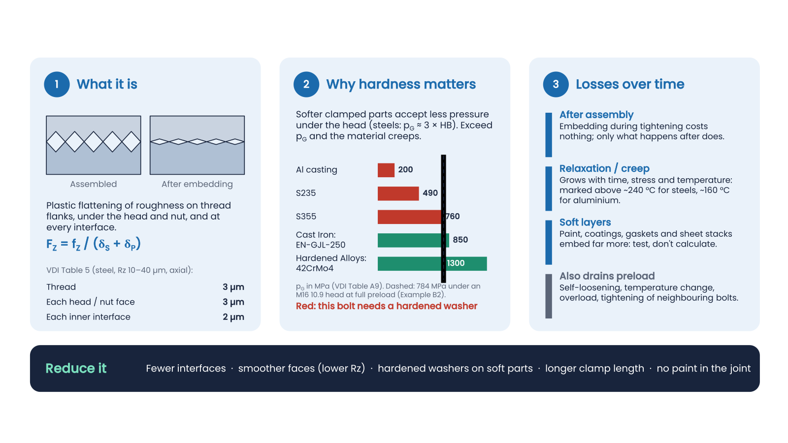
Paint, galvanising, gaskets and stacks of thin sheets embed far more, so test them rather than calculate. Relaxation also grows with time, stress and temperature, markedly above about 240 °C for steels and 160 °C for aluminium. To reduce embedding:
- Use fewer interfaces and smoother faces.
- Fit hardened washers on soft parts, including castings.
- Use a longer clamp length.
- Keep paint and soft coatings out of the joint.
VDI 2230 in 14 steps
VDI 2230 Part 1 turns all of this into a repeatable, checkable calculation in 14 steps, R0 to R13. R0 to R6 work out how much preload the joint needs and the most it could get. R7 to R9 check the bolt can take it, R10 to R12 check the joint, and R13 gives the tightening torque. The loads themselves aren't part of the guideline: they come from your own analysis.
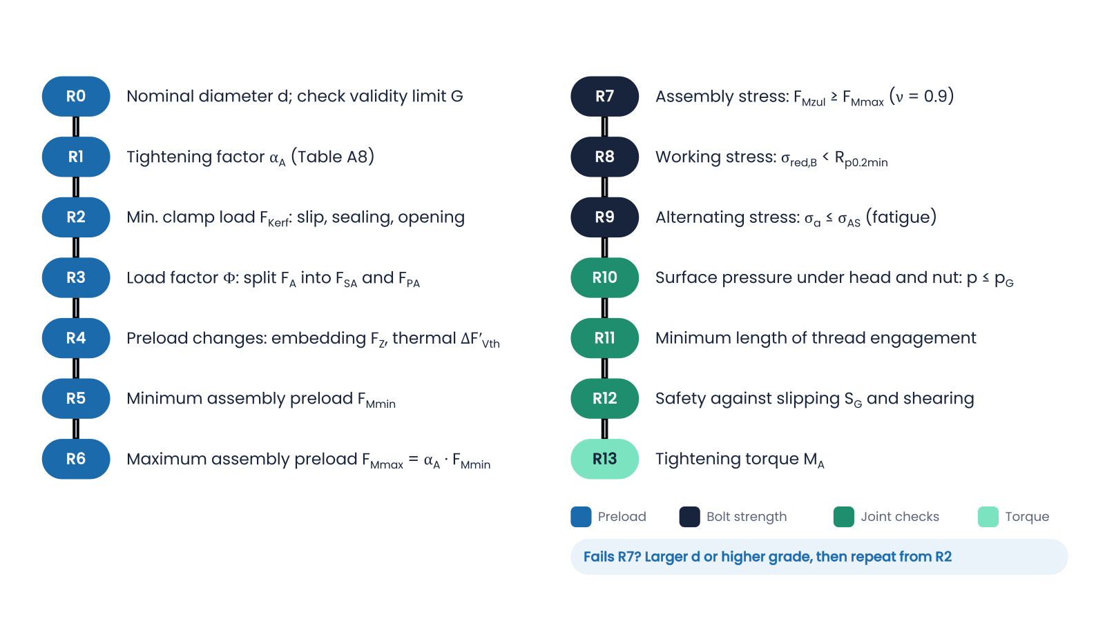
The inputs fall into four groups. Loads: axial, transverse, torsion and bending, and the number of cycles. Geometry: thread size and pitch, clamp length, bearing and hole diameters, plate width and eccentricity. Materials: bolt grade, plate and nut properties, thermal expansion, and whether the threads were rolled before or after heat treatment. Assembly: the tightening method, friction in the thread, under the head and at the interface, and the surface roughness and number of interfaces. In practice the assembly inputs drive the result more than most people expect.
Levers when a check fails
What to change when a check fails
R7
- Problem
- Bolt overloaded in tightening
- Design changes that fix it
- Lower-scatter tightening, a higher grade or larger diameter, lower thread friction
R12
- Problem
- Joint slips
- Design changes that fix it
- More preload, higher interface friction from surface preparation, more bolts or a larger pitch circle, fitted bolts or dowels
R9
- Problem
- Fatigue
- Design changes that fix it
- A lower load factor from longer or waisted bolts or sleeves, threads rolled after heat treatment, no eccentric load or opening
R10
- Problem
- Surface pressure
- Design changes that fix it
- Hardened washers, a larger bearing diameter (flange head), a stronger clamped material
R11
- Problem
- Thread stripping
- Design changes that fix it
- Longer engagement, a stronger nut or tapped material, thread inserts
R4
- Problem
- Too much preload loss
- Design changes that fix it
- Fewer interfaces, smoother faces, a longer clamp length, no paint or soft coatings in the joint
| Check | Problem | Design changes that fix it |
|---|---|---|
| R7 | Bolt overloaded in tightening | Lower-scatter tightening, a higher grade or larger diameter, lower thread friction |
| R12 | Joint slips | More preload, higher interface friction from surface preparation, more bolts or a larger pitch circle, fitted bolts or dowels |
| R9 | Fatigue | A lower load factor from longer or waisted bolts or sleeves, threads rolled after heat treatment, no eccentric load or opening |
| R10 | Surface pressure | Hardened washers, a larger bearing diameter (flange head), a stronger clamped material |
| R11 | Thread stripping | Longer engagement, a stronger nut or tapped material, thread inserts |
| R4 | Too much preload loss | Fewer interfaces, smoother faces, a longer clamp length, no paint or soft coatings in the joint |
The guideline's recommended safety factors are at least 1.2 against fatigue, and against slip 1.2 for static loads and 1.8 for alternating loads.
Worked example: a flange coupling
VDI Example B2 brings the steps together. Twelve M16 10.9 bolts on a 258 mm pitch circle transmit 13 kN·m in both directions by friction between cast iron halves, with an interface friction coefficient of 0.15. Each bolt carries 8.4 kN of transverse load, so it needs 56 kN of clamp. Adding 3.6 kN of embedding gives FMmin = 59.6 kN, and a calibrated torque wrench (αA = 1.6) gives FMmax = 95.4 kN, inside the 118.8 kN the bolt can take. Slip safety is 1.26 against a recommended 1.2, head pressure is 784 MPa against a limit of 850 MPa, and the tightening torque is 302 N·m.
Five situations where intuition gets it wrong
Greased bolts
An M16 10.9 bolt's torque is calculated for a friction coefficient of 0.14: 338 N·m. On site, the fitter adds MoS₂ paste, with a friction coefficient of about 0.08, and uses the same torque. Same torque, same preload? No. Less torque is lost to friction, so more turns into stretch, and the wrench now asks for about 188 kN, roughly 60% more than the 116 kN designed. The bolt yields at about 138 kN and breaks at about 163 kN, before the wrench clicks.
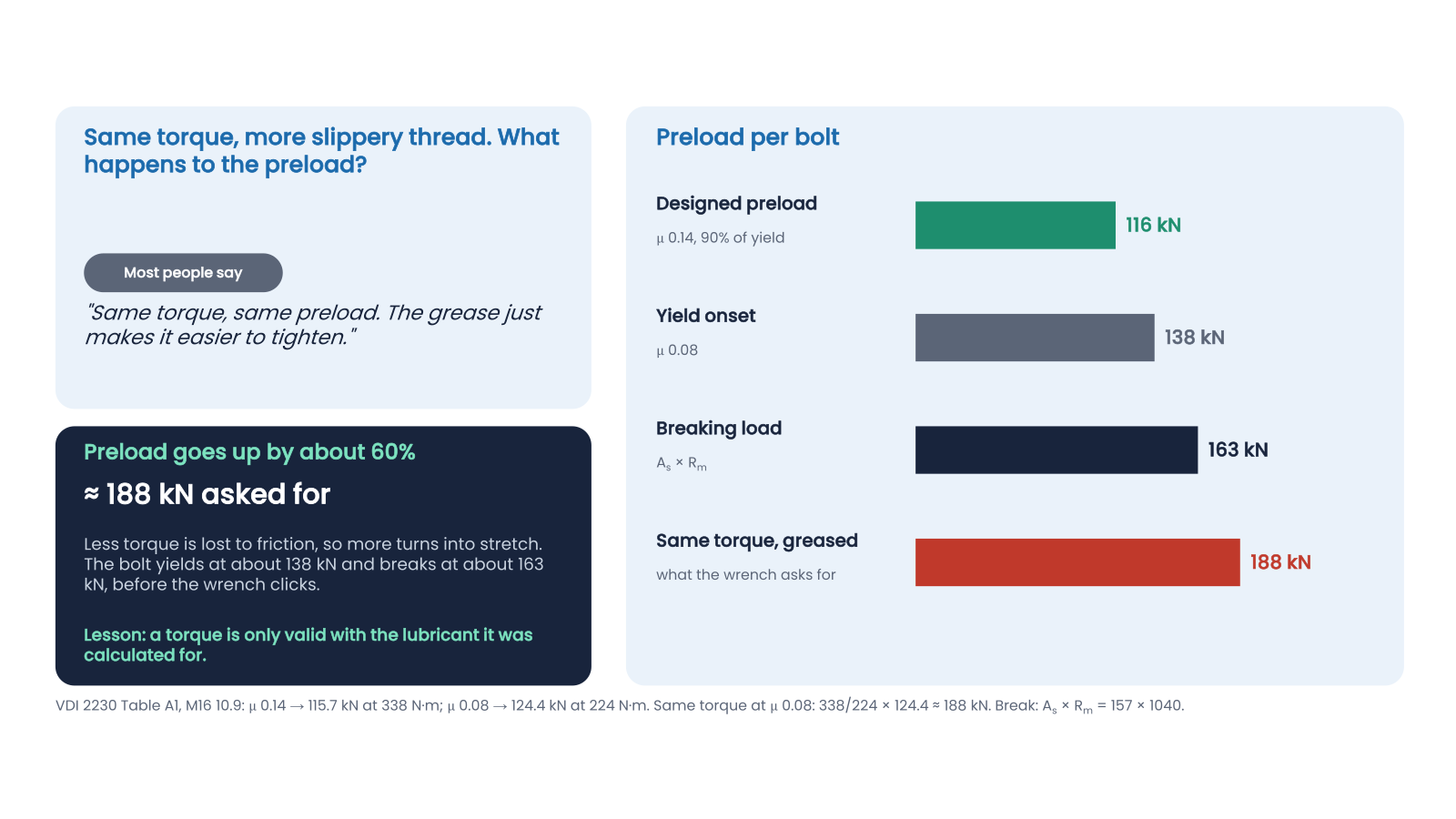
A torque is only valid with the lubricant it was calculated for. Put the lubricant on the drawing next to the torque, and never change one without the other.
Just add a few shims
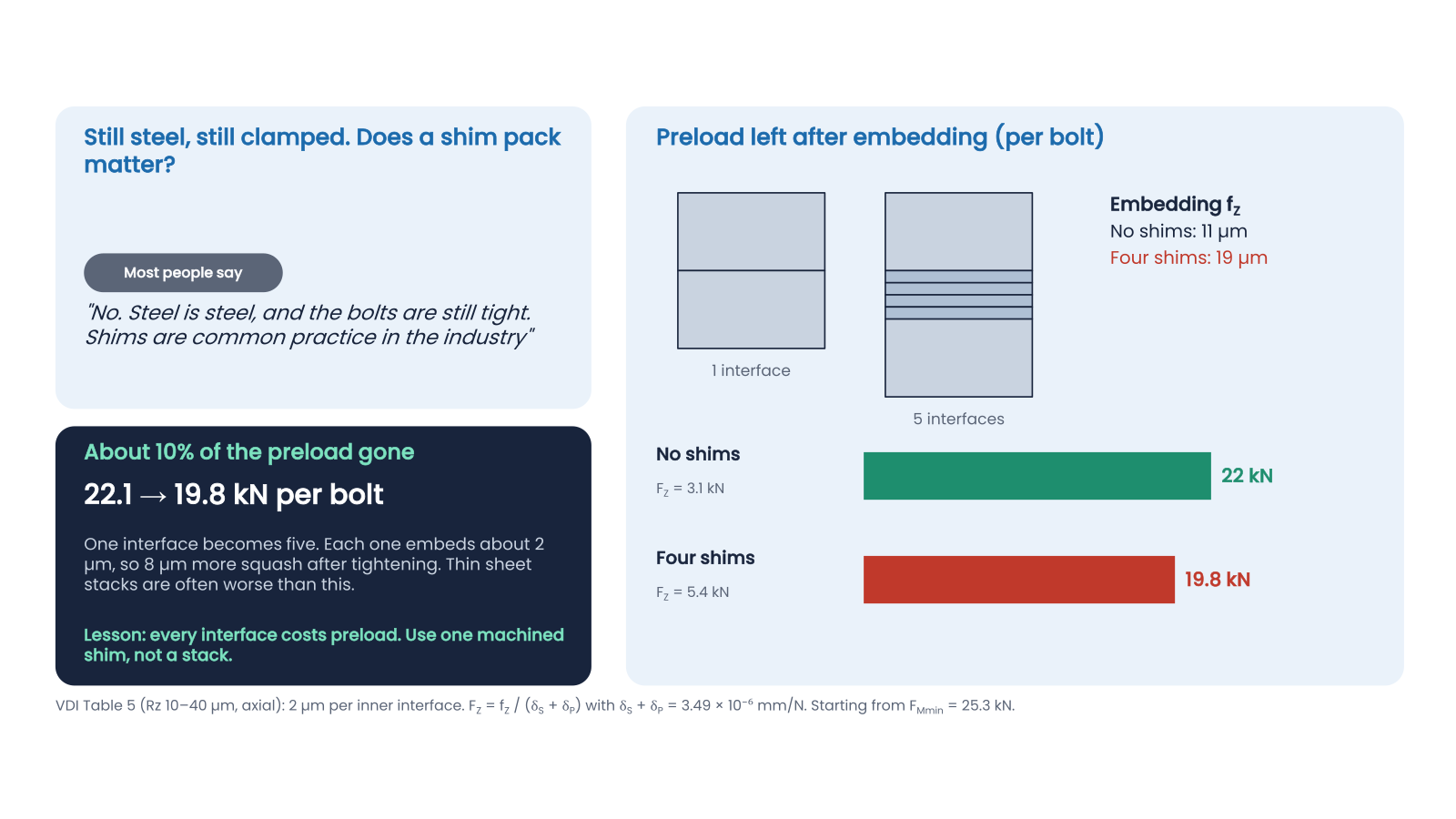
Back to the M12 joint. There's a 2 mm gap on site, so the fitter packs it with four 0.5 mm shims. Steel is steel, surely? But one interface has become five, and each embeds about 2 µm, so the preload left after embedding falls from 22.1 to 19.8 kN per bolt, about 10% less. Thin sheet stacks are often worse than that, and burrs, rust or paint make it worse again. Use one machined shim, not a stack.
It clicked, so it's tight
Six months into service, a maintenance check finds the wrench clicks at the specified torque without the nut turning. That tells you very little. Most of the torque goes into friction, and static friction rises in service through corrosion, fretting and adhesion, so a bolt that has lost much of its preload can still hold the torque. If a torque check is used at all, the click has to come while the nut is moving. To verify the preload on a critical joint, measure stretch or force instead:
- Ultrasonic elongation measures bolt stretch directly, and is the most accurate.
- Load-indicating washers show that a minimum preload was reached at installation.
- Load cells or instrumented bolts give a continuous reading on critical joints.
- Witness marks show whether a nut has turned since tightening. They're cheap and quick to inspect, but they show rotation, not preload.
Squash it harder
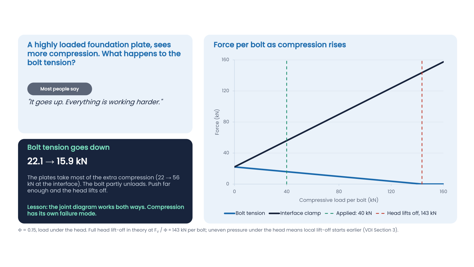
The same M12 joint, at 22 kN per bolt, sits under a heavily loaded foundation plate that now sees 40 kN of compression per bolt. Is the bolt working harder? No: the joint diagram works both ways. The plates take most of the extra compression, rising from 22 to 56 kN at the interface, and the bolt partly unloads, from 22.1 to 15.9 kN. Full lift-off of the head would need about 143 kN per bolt in theory, but pressure under the head is rarely even, so local lift-off starts earlier. A preload that changes with a cyclic load can also feed loosening and fatigue.
Hot or cold?
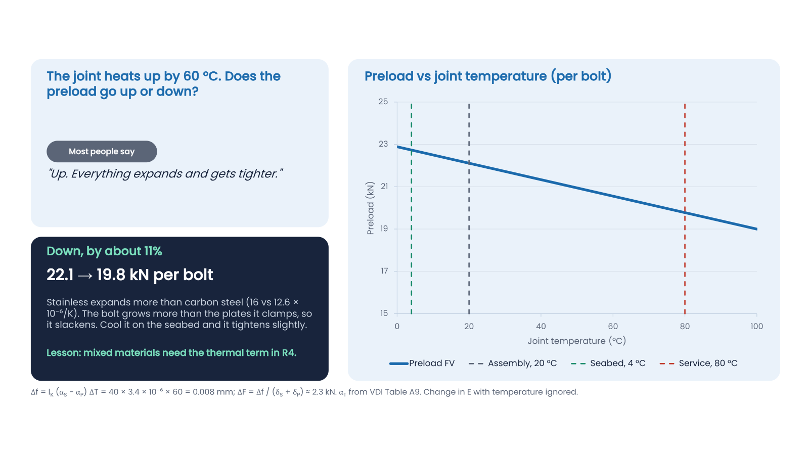
Put the same M12 A4-80 bolts into an S355 flange, assembled at 20 °C and running at 80 °C. Everything expands, so it gets tighter? No. Stainless steel expands more than carbon steel, 16 against 12.6 × 10⁻⁶ per kelvin, so over the 40 mm clamp length the bolt grows 0.008 mm more than the plates and slackens. The preload falls by about 2.3 kN, roughly 11%, to 19.8 kN per bolt: as much as all the embedding. Cool it on the seabed and it tightens slightly, and reverse the materials and heating increases the preload instead. Sunlight, deployment into cold water, process fluids and cryogenic service all bring this into play, and in a transient the answer depends on which part warms first.
Good bolted joint design
Design around preload: get it high, keep it there, and keep the load out of the bolt.
- Geometry: thicker plates and longer bolts lower the load factor and lose less preload to embedding. Keep the pressure cone inside the part, because an edge or cut-out inside it makes the plates softer than the calculation assumes. Put bolts close to the load line and keep flanges stiff to avoid prying and opening.
- Shear: carry it by friction or, in highly loaded shear joints, by close-fitting dowels or pins.
- Holes and washers: avoid oversized or slotted holes in high strength friction grip connections, and use hardened washers on soft parts.
- Installation: leave room for the tools, for maintenance and for holding the nut. Torques above about 500 N·m need large tools or extensions, so several smaller bolts can be more practical than a few large ones. An extension bar on a torque wrench changes the torque it applies.
- Friction: state the lubricant, and match coatings and surface preparation to the assumed friction. A friction value for zinc silicate primer, for example, needs the specified coating type and thickness.
- Locking: correct preload is the best locking. Spring washers don't work in preloaded joints.
- Reuse: reuse bolts only if they were tightened elastically. Our own rule is 70% of yield or less. Bolts tightened to around 90%, where scatter may have taken some past yield, shouldn't be assumed reusable.
- Corrosion: avoid galvanic pairs such as stainless bolts in aluminium subsea, or isolate them with washers designed into the joint.
Where VDI 2230 applies
VDI 2230 Part 1 covers steel bolts with 60° metric threads in grades 8.8 to 12.9 (stainless 70 and 80), where the working load is carried by friction through the clamped parts. Its tables run from M4 to M39. It handles static or dynamic axial load, bending and transverse loads, and concentric or eccentric clamping.
It doesn't find the external loads, treat corrosion, shock or random loads, or cover thread inserts and non-metallic threads, and its material data are room temperature values. It also assumes linear-elastic behaviour and an idealised pressure cone, so gaskets, soft coatings, thin flanges and bolts near an edge all need care. And it doesn't replace testing or FE on critical joints.
Three takeaways
- Preload is the design. The torque is just how you get there.
- Size the bolt for FMmax and the joint for FMmin. The tightening factor links them, so the tightening method matters.
- Stiff joint, compliant bolt. Most of the external load never reaches the bolt.
None of this replaces engineering judgement, and most joints don't need the full method. Where they do, VDI 2230 gives a repeatable way to prove the preload is enough, and not too much. At Subco we're turning this session into written guidance on applying the bolting standards, with standard friction and torque values for the bolt sizes and tools we use most.
Category:
Blog
Written by:

Richard Ward